
Preview: new in the next FireCAD release, planned for December 1, and in the beta available now.
Overview
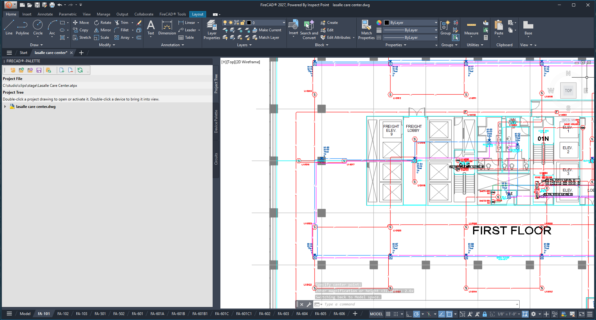
With Auto Draw Wirepaths on, FireCAD draws each circuit's wirepaths for you as you connect devices, and keeps them up to date. Wires stay inside your building outline, go around keep-out areas, walls and other devices, and end at the edge of each device instead of its insertion point. When you connect, disconnect, resequence or move a device, only the wires that changed are redrawn, and their labels and wire fill are updated with them.
Auto Draw Wirepaths is set per project and is off by default, so existing projects keep drawing wirepaths exactly as before until you turn it on.
Commands
| Command | Description |
|---|---|
ATAUTO_DRAW_WIREPATHS_TOGGLE |
Turn Auto Draw Wirepaths on or off for the project |
ATREROUTE_AUTO_WIREPATHS |
Redraw the auto-drawn wires of the circuits you pick |
The older command names ATCIRCUIT_LINES_TOGGLE and ATREROUTE_CIRCUIT_LINES still work and run the same commands.
Prerequisites
- A FireCAD project must be open
- For the wires to stay inside the building, draw the building outline as a closed polyline on the
FA-BOUNDARY-BLDGlayer (or a layer you choose in Options)
Turning It On
Use any of these. They all change the same project setting:
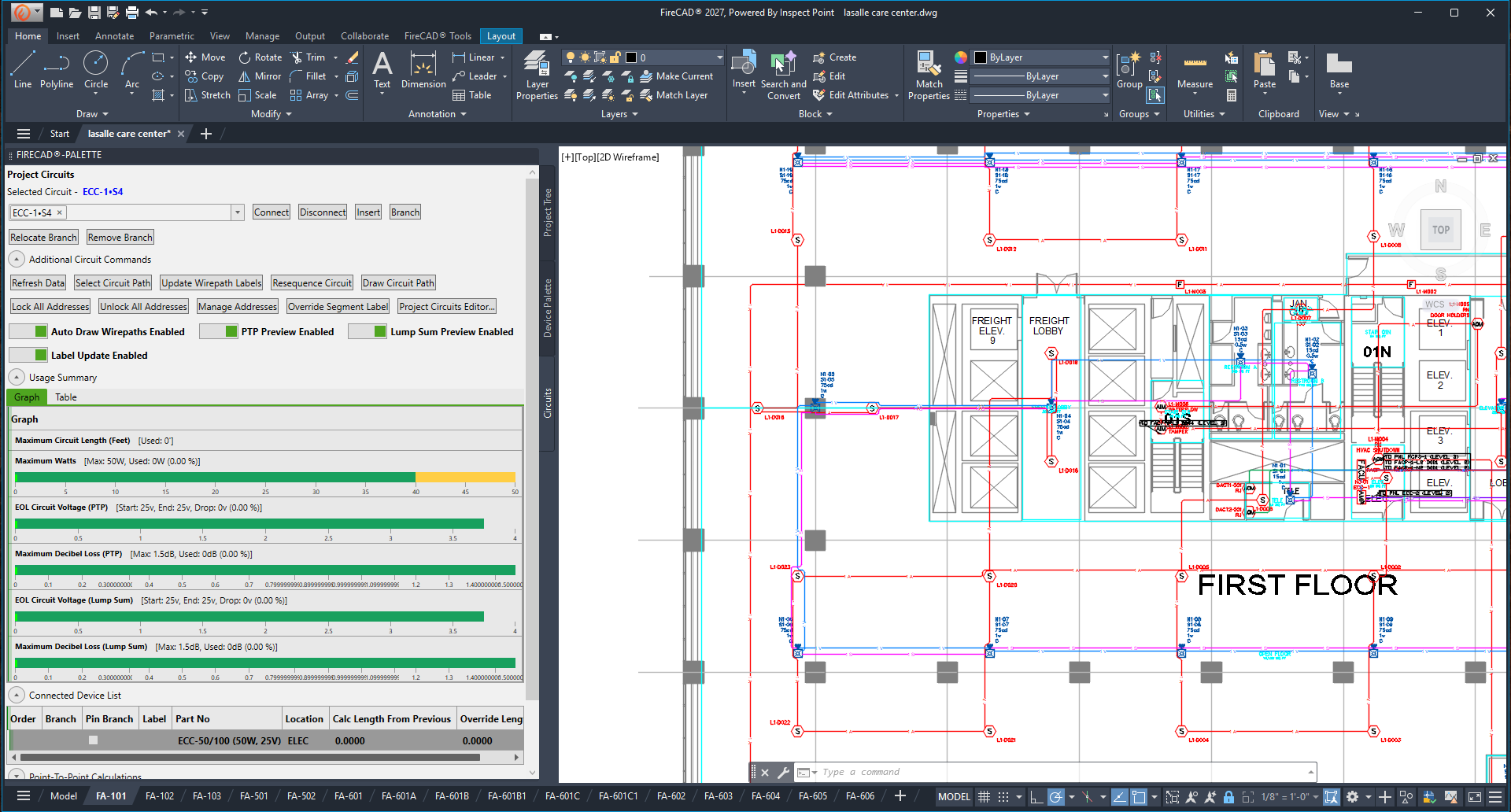
- Project Circuits palette: set the Auto Draw Wirepaths switch to Auto Draw Wirepaths Enabled. It sits with the PTP Preview, Lump Sum Preview and Label Update switches.
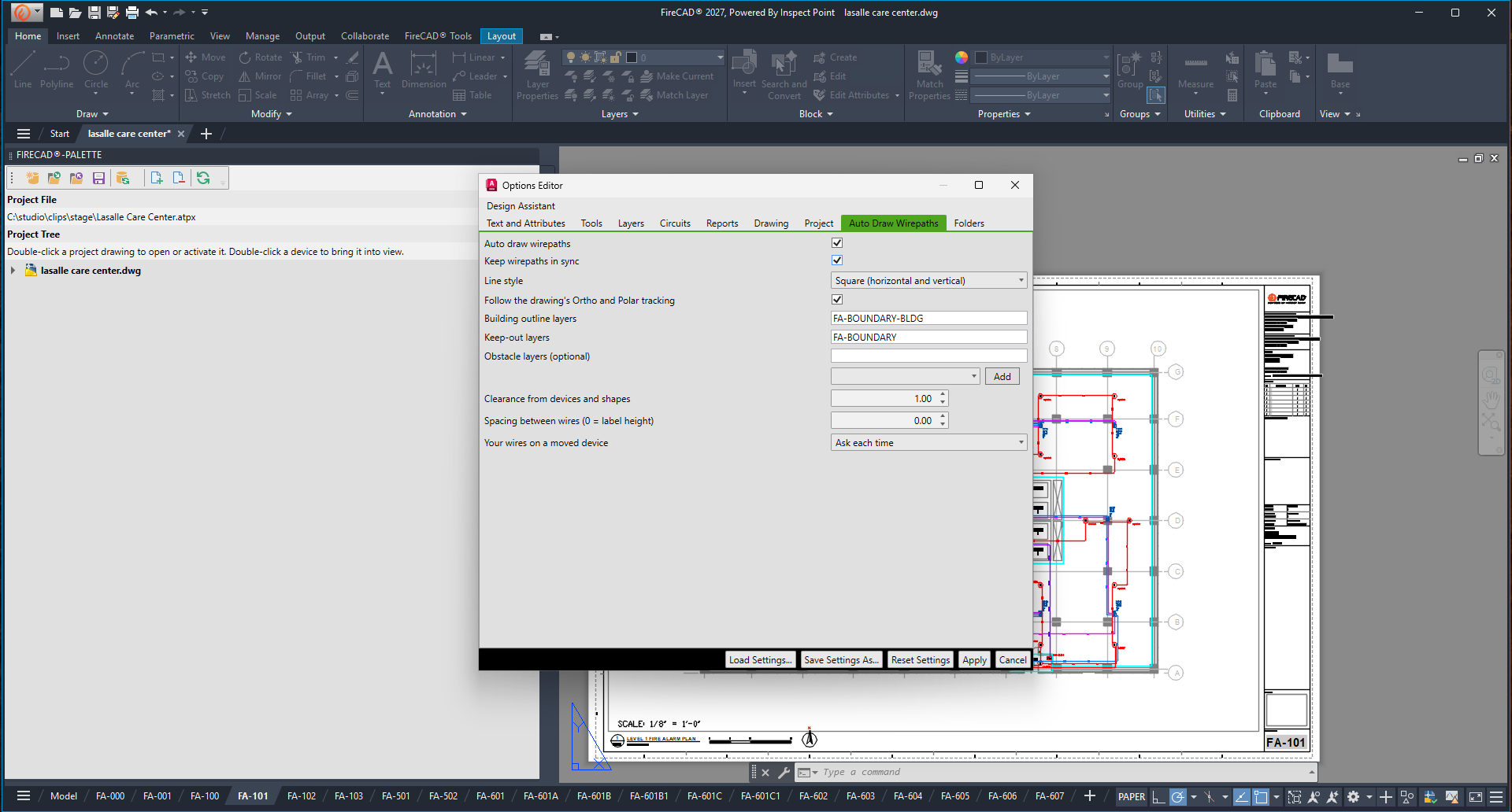
- Options > Auto Draw Wirepaths: tick Auto draw wirepaths and Keep wirepaths in sync, then click Apply.
-
Ribbon: on the FireCAD Tools tab, click Auto Draw Wirepaths On/Off in the Draw panel, or type
ATAUTO_DRAW_WIREPATHS_TOGGLE. FireCAD reports whether it is now on or off.
The first time you connect a device in a project where it is off, FireCAD asks once: "New in this version: FireCAD can draw each circuit's wirepaths for you as you connect devices... Turn it on for this project?"
- Turn It On turns it on for the project and draws the wires for the circuits you just connected.
- Not Now leaves it off. You are not asked again, and you can turn it on later with the palette switch or in Options.
Turning it on does not redraw wires that are already in the drawing. To bring an existing circuit under Auto Draw Wirepaths, draw or reroute its wirepaths (see Rerouting Auto-Drawn Wires below).
Options > Auto Draw Wirepaths
| Setting | Default | What it does |
|---|---|---|
| Auto draw wirepaths | Off | FireCAD draws each circuit's wirepaths for you, inside the building outline and around keep-outs and devices |
| Keep wirepaths in sync | Off (on when you use the palette switch, the toggle command or the prompt) | Redraws only the affected wires when you connect, disconnect, resequence or move devices |
| Line style | Square (horizontal and vertical) | Square runs only horizontal and vertical in the current UCS. Direct (any angle) takes the shortest way. A circuit template can set its own style |
| Follow the drawing's Ortho and Polar tracking | On | When Ortho or Polar tracking is on in the drawing, wires use those angles instead of the line style |
| Building outline layers | FA-BOUNDARY-BLDG |
Closed polylines on these layers are the building outline; wires stay inside. Separate names with commas; * and ? work |
| Keep-out layers | FA-BOUNDARY |
Shapes on these layers are areas wires go around, by their real shape |
| Obstacle layers (optional) | Blank | Walls or equipment to route around, for example A-WALL*. Layers inside attached floor plans (xrefs) count too. Pick a layer from the list and click Add
|
| Clearance from devices and shapes | 1 | Gap kept between a wire and devices, keep-outs and the inside of the building outline (drawing units at scale 1) |
| Spacing between wires (0 = label height) | 0 | Gap kept between parallel wires so their labels stay readable. 0 uses the label height |
| Your wires on a moved device | Ask each time | What happens to wires you routed yourself when you move or turn a device they connect to (see below) |
Off and frozen layers are ignored. Lines and open polylines on an obstacle layer act as thin walls.
Line style per circuit template. A circuit template can override the project's line style, for example direct runs for SLC loops and square runs for NACs. Set the Auto Draw Wirepath Style column on the circuit template in the project Device Editor: blank uses the project setting, 0 is square, 1 is direct. When the project follows the drawing's Ortho and Polar tracking and one of them is on, the drawing's angles still win.
What Happens as You Work
| You do this | Auto Draw Wirepaths does this |
|---|---|
| Connect or insert a device | Draws the new leg(s) only |
| Disconnect a device | Removes its legs and closes the gap |
| Resequence or relocate devices | Redraws the legs whose order changed |
| Move, stretch, rotate or scale a device (including grip moves) | Redraws the wires to that device |
| Undo | One U undoes everything one update changed |
A route that cannot avoid every device takes the way with the fewest crossings, and FireCAD reports it. Legs that cannot be routed at all are drawn straight, and the command line says how many.
What it leaves alone
Auto Draw Wirepaths only erases and redraws wires it drew itself. It never changes:
- Wires you draw yourself (Quick Poly, Poly, Spline, or a plain AutoCAD line or polyline picked up as a segment). FireCAD never draws a second wire beside a wire you routed.
- Wires on locked circuits.
- Wires you filtered to particular circuits or circuit types.
- Wires with a label override (see Overriding Segment Labels (Preview)).
When an update would have changed such wires but kept them, the command line says so once, for example: "Auto draw wirepaths: 3 wires left as they are: 2 have a label override, 1 was drawn by hand. Use Reroute Auto Drawn Wirepaths to replace them."
Your wires on a moved device
When you move or turn a device that has wires you routed yourself, FireCAD asks what to do with them, unless you chose an answer in Options:
- Reroute Them: the same wires get a new route. Their labels, overrides and filters stay.
- Move Their Ends Only: each wire keeps its shape; its end at the device follows the device.
- Leave Them: nothing changes. No second wire is drawn beside them.
Tick Don't ask again for this project to keep your answer. To be asked again, set Your wires on a moved device back to Ask each time in Options > Auto Draw Wirepaths. The other choices there are Always reroute, Always move the ends and Always leave them.
Rerouting Auto-Drawn Wires
-
On the FireCAD Tools tab, click Reroute Auto Drawn Wirepaths in the Draw panel, or type
ATREROUTE_AUTO_WIREPATHS -
Select devices or wires on the circuits to reroute, then press Enter
-
If any of those wires have a label override or were drawn by hand, FireCAD asks "Replace them too?"
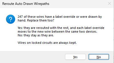
- Yes: they are rerouted with the rest, and each label override moves to the new wire between the same two devices
- No: they stay as they are
-
The command line reports how many circuits and wires were redrawn
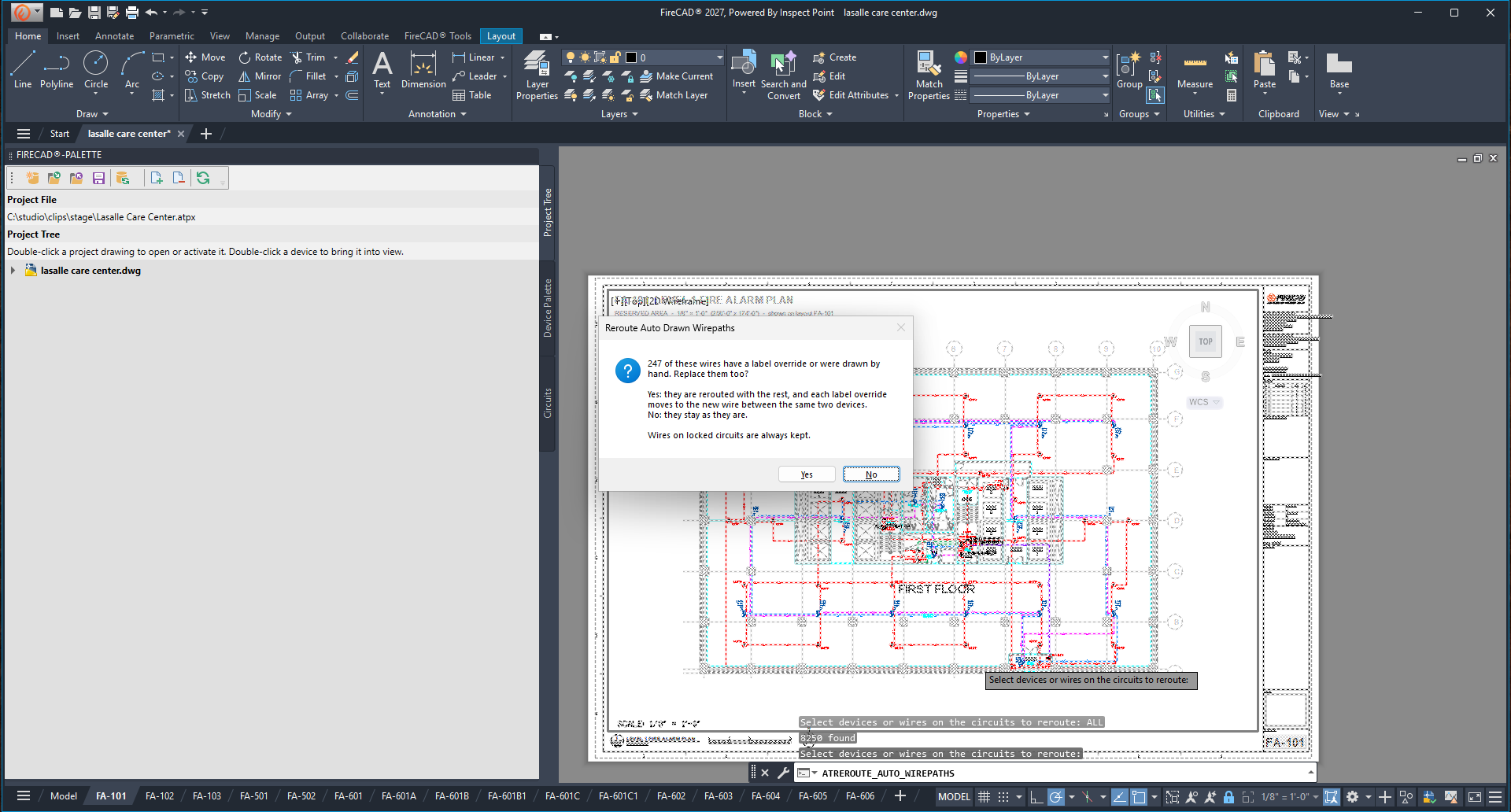
Wires on locked circuits are always kept. The command needs Auto Draw Wirepaths to be on for the project.
Wire Status Markers
With Show Wirepath Status Icons In Model Space on (Options > Circuits), each wire Auto Draw Wirepaths will not change carries one marker, so you can see why at a glance:
| Marker | Meaning |
|---|---|
| Red LCK | The wire is on a locked circuit |
| Amber OVR | The wire has a label override, or still carries a circuit pair |
| Cyan USR | You routed the wire yourself |
The markers are drawn on the Defpoints layer and never print.
Tips
- Draw the building outline first. Without one, wires are not contained.
- Currently, wires that were in the drawing before you turned Auto Draw Wirepaths on, or that were drawn while it was off, do not follow a moved device. Run
ATREROUTE_AUTO_WIREPATHSon those circuits once to bring them under Auto Draw Wirepaths. - The Design Assistant can also turn Auto Draw Wirepaths on and draw the wirepaths for a whole floor when you ask it to.
- Turning it off (
ATAUTO_DRAW_WIREPATHS_TOGGLEor the palette switch) leaves the wires already drawn in place; FireCAD just stops updating them.
Related Commands
- Auto-Draw Circuit Wirepath
- Auto-Draw Active Wirepath
- Auto-Draw Shared Wirepath
- Overriding Segment Labels (Preview)
- Project Circuits Palette (Preview)
FireCAD is the industry-leading AutoCAD add-in for fire alarm system design — from circuit layout to wire routing to code-compliant reports.
Learn more and get started at getfirecad.com →
Inspect Point Integration — Fire alarm system device lists and bill of materials can be pushed directly from FireCAD into Inspect Point, eliminating manual data entry and ensuring every device is ready for inspection scheduling and ongoing asset management.
Learn more here →