
Preview: this page describes the next FireCAD release, planned for December 1, and the beta available now. For the current release, see Battery Calculations.
Watch the Video
Open the video in a new tab (Battery Calculation Report, 57 seconds).
Commands
| Command | Description |
|---|---|
ATREPORT_BATTERY_CALCS |
Place the battery calculation report in the drawing |
ATEXPORT_BATTERY_CALCULATIONS |
Export battery calculation reports to Excel |
Ribbon: FireCAD > Reports > Battery Calculation Report (in the drawing). The Excel export is on the Export panel.
Prerequisites
- A FireCAD project must be open
- The panel or power supply must have Generate Battery Calc turned on and a battery size list in the catalog
Overview
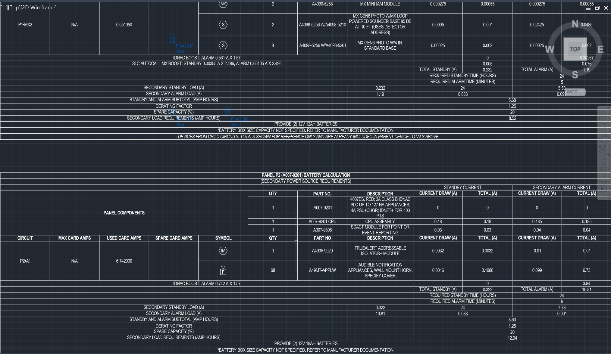
The battery calculation sizes the standby battery for each panel and power supply per NFPA 72. It lists standby and alarm current for the panel's own components and for every circuit, adds any battery boost, and works out the amp-hours the batteries must supply.
Steps
- Click Battery Calculation Report on the Reports panel, or type
ATREPORT_BATTERY_CALCS. To get an Excel file instead, use the Export panel or typeATEXPORT_BATTERY_CALCULATIONS. - In the report window, check the panels to include.
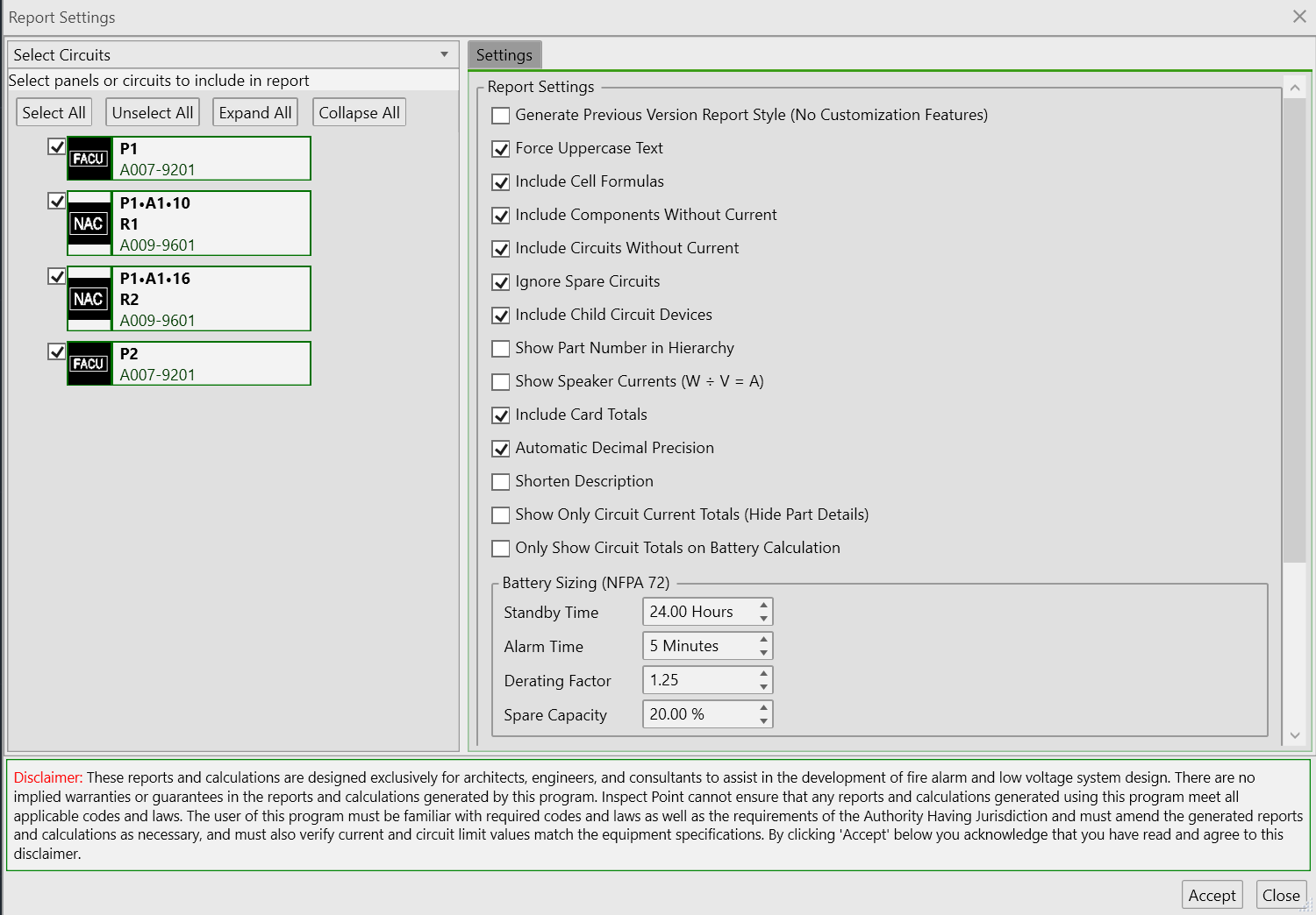
- Open the Settings pane to check the battery sizing values and report options (see below).
- Click Accept.
Calculation Formula
Standby AH  = Total Standby Current x Standby Time (hours)
Alarm AH    = Total Alarm Current x Alarm Time (minutes) / 60
Required AH = (Standby AH + Alarm AH) x Derating Factor x (1 + Spare Capacity % / 100)
The totals already include any battery boost (see below). When Spare Capacity is 0 the last term is 1 and the formula is the same as in earlier releases.
Default values:
| Setting | Default |
|---|---|
| Standby Time | 24 hours |
| Alarm Time | 5 minutes (15 minutes on a voice project, see below) |
| Derating Factor | 1.25 |
| Spare Capacity | 0 % |
Where the Settings Are
The four battery sizing values are project settings. You can change them in either place; both edit the same value.
- Options > Reports > Battery calculation (NFPA 72): Standby Time, Alarm Time, Derating Factor, Spare Capacity, and Only Show Circuit Totals on Battery Calculation.
- Report window > Settings > Battery Sizing (NFPA 72): Standby Time, Alarm Time, Derating Factor and Spare Capacity.
Spare Capacity
Spare Capacity is a percentage added on top of the derating factor, for designs that must keep spare battery capacity (for example 20 %). Required AH = AH x derating x (1 + spare). When it is above 0, the report prints a SPARE CAPACITY (%) line under DERATING FACTOR, and the SECONDARY LOAD REQUIREMENTS (AMP HOURS) line includes it. When it is 0, the line is not printed.
The Design Assistant has its own spare capacity preference on the Design Assistant tab of Options. That one is the margin the assistant designs to; the report always uses the project setting above.
Voice Projects Use 15 Minutes of Alarm
NFPA 72 requires 15 minutes of alarm for an emergency voice/alarm communication system. When the project has speaker circuits (any circuit that appears on the decibel loss report and has at least one device), FireCAD uses at least 15 minutes of alarm for every panel in the project. A higher Alarm Time setting still wins. Your saved setting is not changed, and REQUIRED ALARM TIME (MINUTES) on the report shows the time actually used.
Battery Boost (IDNAC and MX Loop)
Some circuits run above the 24 V their devices' currents are rated at, so the battery supplies more than the devices' stated current. FireCAD multiplies that current and prints the extra as its own line:
| Circuit | Multiplier | Applies to |
|---|---|---|
| Autocall / Simplex IDNAC | 1.57 | Alarm current |
| IDNAC behind an IDNAC repeater (A009-9601 / A009-9602) | 1.37 | Alarm current |
| Autocall ES-MX loop | 2.496 | Standby and alarm current |
The boost line reads, for example, IDNAC BOOST: alarm 0.708 A x 1.57, and its value (0.708 x 0.57) is added to the alarm total. The boost is used in the battery calculation and the Panel Summary only. It never changes voltage drop.
The multiplier can be set at three levels. The most specific one wins:
- Circuit type: Master Template Editor (or the project Device Editor), Circuit Types pane, columns Battery Standby Multiplier and Battery Alarm Multiplier. Blank means 1.
- Circuit template: Panel Circuit Templates (Output) pane, columns Battery Standby Multiplier (overrides type) and Battery Alarm Multiplier (overrides type). Blank means use the type's value.
- One circuit: Project Circuits Editor, columns Battery Standby Multiplier and Battery Alarm Multiplier. Blank means inherit. Enter 1 to switch the boost off on that circuit.
Important: A template or circuit value only changes the boost for device connections whose circuit type already has a multiplier. It does not boost other devices on the circuit. A value of 1 or less means no boost. Power-limited circuits counted at their circuit limit are not boosted.
For the full Autocall and Simplex background, see Autocall and Simplex Update.
Battery Size Selection
FireCAD sizes the battery automatically. It picks the smallest battery in the panel's available size list that meets the calculated required AH, so it lands on a smaller battery (for example 12V 8AH) whenever that size covers the load, and steps up only when the requirement exceeds it.
To make the calculation reflect a larger battery than the one it selects (for example 12V 18AH instead of 12V 8AH):
- Change the minimum battery size for that panel so the calculation starts at the larger battery, or
- Type the size you want directly into the battery-size field in the battery calculation table.
If the size you need is not offered for a panel, contact support to have it added to the panel's battery list.
Report Options
The Settings pane of the report window holds the options for this report. The ones that matter most for the battery calculation:
- Show Speaker Currents (W ÷ V = A): converts speaker wattage to alarm current using the circuit voltage, so speakers count in the battery calculation
- Include Card Totals: shows the MAX / USED / SPARE CARD AMPS columns
- Include Child Circuit Devices: includes devices on circuits fed through riser (passthrough) devices
- Include Components Without Current and Include Circuits Without Current: list items with zero current
- Ignore Spare Circuits: leaves out circuits with no devices
- Include Cell Formulas: writes Excel formulas instead of plain values
- Show Only Circuit Current Totals (Hide Part Details) and Only Show Circuit Totals on Battery Calculation: collapse devices to circuit totals
- Automatic Decimal Precision: amp-hours and battery sizes keep their decimals when this is off
Panel Summary
The Panel Summary Report uses the same totals, including the boost line. It shows standby and alarm current separately, and a card's used amps is the larger of its standby and alarm current, not their sum.
Tips
- NFPA 72 Section 10.6.7.2 defines the standby and alarm time requirements
- Re-run the report after changing a multiplier, the spare capacity or the alarm time
Related Articles
FireCAD is the industry-leading AutoCAD add-in for fire alarm system design — from circuit layout to wire routing to code-compliant reports.
Learn more and get started at getfirecad.com →
Inspect Point Integration — Fire alarm system device lists and bill of materials can be pushed directly from FireCAD into Inspect Point, eliminating manual data entry and ensuring every device is ready for inspection scheduling and ongoing asset management.
Learn more here →