
Preview: this page describes the next FireCAD release, planned for December 1, and the beta available now. For the current release, see Riser Diagram V2.
Command
| Command | Description |
|---|---|
ATRISER |
Open the Riser Options dialog to create a riser diagram |
ATRISER_SELECTION |
Create a riser diagram from selected passthrough devices |
Ribbon: FireCAD > Riser > Create Riser Diagram
Overview
The Riser V2 update introduces a redesigned options dialog, per-circuit layout controls, dynamic color preview, and improved layout algorithms. This article covers all settings and features available in the Riser Options dialog, including the changes in the December 2026 release: Separate Column Per Riser Circuit and the overlapping-circuits prompt, Auto-Align Vertical Runs on multi-floor circuits, Draw Left on networked panels, wrapped circuits that keep their child circuits, and origin entity-property values in the circuit list. Isolate Riser Circuit Columns has been retired.
Riser Options Dialog
The dialog is split into two panes. The Select Circuits pane on the left contains the circuit selection TreeView with per-circuit settings. The Riser Settings pane on the right contains layout settings and display options.
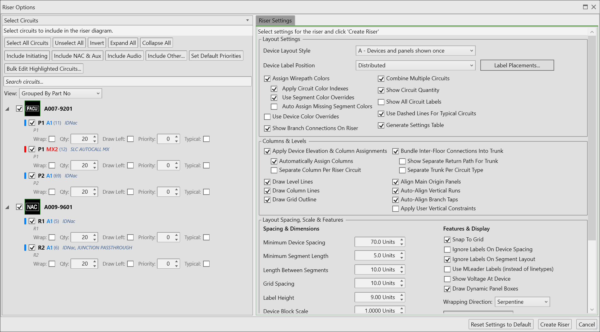
Riser Settings Pane: Layout Settings
Device Layout Style
Controls the overall layout algorithm for the riser diagram.
| Style | Description |
|---|---|
| Non-Duplicating (A) | Devices and panels shown once. Default for most projects. |
| Legacy (B) | Devices duplicated per circuit, panels shown once |
| Duplicating (C) | All circuits and panels duplicated |
| Wirepath (D) | Devices follow floorplan wirepath layout |
| Summary (E) | Devices summarized by elevation with quantities |
Device Label Position
Controls where labels appear relative to device blocks. When Distributed is selected, a Label Placements... button appears next to it for choosing which corner each label group (address, voltage, candela, and so on) appears in.
| Position | Description |
|---|---|
| Top Left | Labels above and to the left of the device |
| Top Center | Labels centered above the device |
| Top Right | Labels above and to the right of the device |
| Bottom Left | Labels below and to the left of the device |
| Bottom Center | Labels centered below the device |
| Bottom Right | Labels below and to the right of the device |
| Distributed | Labels split into four corners around each device (default) |
Distributed Label Mode
When Distributed is selected, device information is split across four corners of each device block for improved readability:
- Lower-right: Circuit addresses and voltage at device
- Upper-right: Settings (candela, watts, decibels)
- Upper-left: Custom entity properties
- Lower-left: Entity properties and EX (existing) marker
Color Settings
Colors are resolved using a tiered cascade. Each tier is controlled by a checkbox.
| Setting | Description |
|---|---|
| Assign Wirepath Colors | Master toggle: disables all color settings when unchecked |
| Apply Circuit Color Indexes | Uses the color assigned to the circuit in the database |
| Use Segment Color Overrides | Uses origin entity color overrides from the drawing |
| Auto Assign Missing Segment Colors | Automatically assigns colors by circuit type when no color is set |
| Use Device Color Overrides | Applies individual device color overrides |
When Auto Assign Missing Segment Colors is enabled, circuits are colored by type:
| Circuit Family | Color |
|---|---|
| SLC | Red |
| NAC / IDNAC / Horn / Strobe | Blue |
| IDC / IDNET | Cyan |
| Audio / Digital Audio | Magenta |
| Access Control / AOR / Card Reader | Green |
| Wireless / CWSI / SWIFT | Cyan-Green |
| Communication Bus (ARCNET, RS-485, P-LINK, etc.) | Violet |
Combo circuits (containing multiple type families) receive a slightly shifted shade. Unknown types use a stable hash-based color from a built-in palette.
Display Options
| Setting | Description |
|---|---|
| Show Branch Connections On Riser | Display T-tap/branch connection markers |
| Combine Multiple Circuits | Merge shared segments between circuits |
| Show Circuit Quantity | Display device counts on circuit labels |
| Show All Circuit Labels | Each device shows the address labels for every non-origin circuit it is connected to, including circuits not selected for this riser (A, B and C risers) |
| Use Dashed Lines For Typical Circuits | Typical circuits use dashed line styles |
| Generate Settings Table | Place an AutoCAD Table alongside the riser showing the settings used |
| Use MLeader Labels (instead of linetypes) | Use MLeader annotations for line type labels instead of linetypes |
| Show Voltage At Device | Display voltage values next to devices (see Voltage Display below) |
| Draw Dynamic Panel Boxes | Draw automatic panel grouping boxes around origin devices |
Entity Properties
Click Select Entity Properties... to choose which custom entity properties to display on each device in the riser diagram. If any properties are selected, they appear in the label area corresponding to the selected label position (or in the upper-left corner when using Distributed mode).
Columns & Levels
This group is unavailable for the Duplicating (C) layout.
| Setting | Description |
|---|---|
| Apply Device Elevation & Column Assignments | Enable grid-based layout mode (master toggle) |
| Automatically Assign Columns | Auto-assign column values when user assignment is not set |
| Separate Column Per Riser Circuit | Give each circuit that runs between floors its own grid column, so circuits do not draw on top of each other. Available only when both options above are on (see below) |
| Draw Level Lines | Draw horizontal lines at floor/elevation boundaries |
| Draw Column Lines | Draw vertical lines at column boundaries |
| Draw Grid Outline | Draw outer grid frame |
| Bundle Inter-Floor Connections Into Trunk | Combine vertical inter-floor connections into a shared trunk |
| Show Separate Return Path For Trunk | Draw the return path separately from the supply path |
| Separate Trunk Per Circuit Type | Create individual trunk columns per circuit type instead of one shared trunk |
| Align Main Origin Panels | Line up the main origin panels in each column vertically. User-set constraints take precedence |
| Auto-Align Vertical Runs | Line up each multi-floor circuit in a single vertical column instead of stepping over at each floor (on by default; see below) |
| Auto-Align Branch Taps | Stack a circuit's main-line branch devices into one vertical column so branches flow horizontally in rows. User-set constraints take precedence |
| Apply User Vertical Constraints | Honor user-specified same-level constraints set with Set Vertical Constraints |
Note: Isolate Riser Circuit Columns is no longer offered. It moved every circuit's floor-to-floor devices into one shared column; Separate Column Per Riser Circuit and Auto-Align Vertical Runs replace it. A project that had it turned on simply no longer applies it.
Spacing & Sizing
| Setting | Default | Description |
|---|---|---|
| Minimum Device Spacing | 70 | Distance between devices |
| Minimum Segment Length | 5 | Minimum edge length |
| Length Between Segments | 10 | Inter-segment gap |
| Grid Spacing | 10 | Snap-to-grid interval |
| Label Height | varies | Riser text height |
| Device Block Scale | varies | Block reference scale factor |
| Segment Fillet Radius | 4 | Edge corner rounding radius |
| Line Type Label Spacing | 100 | Distance from edge to line type label |
| Line Type Label Height | 6 | Height of line type labels |
| Trunk Junction Box Width | 30 | Width of inter-floor trunk junction boxes |
| Panel Box Width | 100 | Width of dynamic panel boxes |
| Row & Column Padding | 10 | Grid cell padding |
Additional Layout Options
| Setting | Description |
|---|---|
| Snap To Grid | Snap riser elements to the configured grid spacing |
| Ignore Labels On Device Spacing | Exclude labels from device distance calculations |
| Ignore Labels On Segment Layout | Exclude labels from edge routing |
Wrapping Direction
Controls how wrapped circuit rows flow when per-circuit wrapping is enabled.
When a wrapped circuit includes a device that originates its own circuit (for example a module's zone circuit, such as Z01, or a duct detector's remote test station, RTS), that child circuit stays with its device on the wrapped row instead of being drawn in a separate band.
| Style | Description |
|---|---|
| Serpentine | Alternating left-to-right and right-to-left rows (zigzag pattern). This is the default. |
| Left to Right | All rows flow in the same direction |
Select Circuits Pane: Circuit Selection
Panel-Grouped TreeView
Circuits are organized under their parent panel in a TreeView. This replaces the previous flat grid layout.
Panel Row displays:
- Three-state checkbox: Check/uncheck all circuits under the panel at once. Shows indeterminate when some circuits are selected.
- Block image: Thumbnail of the panel's block definition
- Panel name and part number
Circuit Row (nested under panel) displays:
- Color swatch: Live preview of the resolved color (updates dynamically with color settings)
- Include checkbox: Toggle circuit inclusion in the riser
- Circuit name: Displayed in the resolved color, without the panel prefix
- Device count: Number of non-origin devices on the circuit
- Circuit types: Actual connection types from device data (e.g., SLC MODULES, NAC HORNS)
Origin entity properties: when you have chosen entity properties with Select Entity Properties..., each origin's values for those properties (for example building, floor or zone) show as a small grey line under the panel row in Grouped By Panel view, and under each circuit row in the other views. Hover over the line to see all of it. The search box matches these values too.
View Modes
Choose a view from the View: list above the circuit list:
- Grouped By Part No: circuits grouped by origin device part number (default)
- Grouped By Panel: circuits grouped by panel
- Compact (Flat List): circuits in one list, no grouping
Search
A search box at the top (Search circuits...) filters circuits and panels as you type. It matches panel name, part number, circuit name, circuit types and the origin entity-property values.
Per-Circuit Inline Settings
Each circuit row shows editable settings on a second line:
| Setting | Description |
|---|---|
| Wrap | Enable line wrapping for this circuit |
| Qty | Number of devices per row when wrapping (default: 20) |
| Draw Left | Draw this circuit right-to-left (see Draw Left / Right-to-Left Circuits below) |
| Priority | Numerical priority for layout ordering (1 = highest, 0 = no priority) |
| Typical | Mark as typical wiring: drawn with dashed lines, does not drive layout |
Toolbar
| Button | Description |
|---|---|
| Select All Circuits / Unselect All / Invert | Bulk selection controls |
| Expand All / Collapse All | Control TreeView expansion |
| Include Initiating / Include NAC & Aux / Include Audio / Include Other... | Quick-select circuits by type family |
| Set Default Priorities | Auto-assign: SLC/IDC = 1, NAC/Aux = 2, Audio = 3 |
| Bulk Edit Highlighted Circuits... | Edit settings for multiple Ctrl/Shift-selected circuits at once |
Feature Details
Typical Circuit Wiring
Circuits marked as Typical represent standard wiring patterns without duplicating devices in the riser diagram.
- Typical circuits are drawn with dashed lines and display only the circuit name
- Normal circuits continue to drive device placement and layout
- Toggle per-circuit via the Typical checkbox
- The Use Dashed Lines For Typical Circuits global setting controls the dashed vs solid style
Dynamic Color Preview
The circuit list shows a live preview of each circuit's resolved color. Colors update in real time when you toggle the color checkboxes in the settings panel. The preview matches the color the riser drawing engine will produce.
Voltage Display
When Show Voltage At Device is enabled, voltage values are displayed next to each non-origin device in the riser diagram.
- Voltage labels appear below the circuit address on each device
- When voltage drops below the circuit's MinVoltage threshold, the label is displayed in red as a visual warning
- Voltage is calculated per-circuit: multi-circuit devices show voltage only for selected circuits
- Voltage is not shown on Summary (E) risers since summarized devices do not have meaningful individual voltage values
Separate Column Per Riser Circuit
With Bundle Inter-Floor Connections Into Trunk off, every circuit that runs between floors normally shares one grid column, and the circuits draw on top of each other. Separate Column Per Riser Circuit gives each of those circuits its own column, which usually untangles the riser.
- It requires Apply Device Elevation & Column Assignments and Automatically Assign Columns. Without both, the checkbox is greyed out and is not applied, but it keeps its setting for when you turn them back on.
- It is off by default, so existing risers draw as before.
- It is most useful with Bundle Inter-Floor Connections Into Trunk off.
Overlapping Circuits Prompt
When you create an A or B riser with trunks off and Separate Column Per Riser Circuit off, and the circuits that span floors cross each other many times, FireCAD prints a hint on the command line after you place the riser:
This riser has <n> places where different circuits cross. With trunk lines off, Riser Options > Columns & Levels > Separate Column Per Riser Circuit gives each circuit its own column and usually untangles this.
The first time this happens on a project, a Riser circuits overlap message also asks: Turn on Separate Column Per Riser Circuit for this project?
- Yes turns the option on. Run the riser again to see the result.
- No leaves it off and stops asking on this project. The command-line hint still appears.
Auto-Align Vertical Runs
Auto-Align Vertical Runs (on by default) lines up each multi-floor circuit's run into a single vertical column instead of stepping one column to the right at each floor. In this release it also applies to circuits that cross floors, which previously still drew as a staircase. Devices blocking the column are moved right. Wrapped circuits are not affected.
Draw Left / Right-to-Left Circuits
The Draw Left per-circuit setting reverses the layout direction for individual circuits, drawing them from right to left instead of the default left to right.
- When enabled, the circuit's column assignments are mirrored so the circuit flows in the opposite direction
- Child circuits automatically inherit the Draw Left setting from their parent circuit through passthrough device relationships
- When a riser contains both left-to-right and right-to-left circuits, trunk bundles are split so each direction gets its own isolated trunk column
- The C riser (Duplicating layout) also supports Draw Left with proper column mirroring
- Draw Left needs columns. Turn on Apply Device Elevation & Column Assignments and Automatically Assign Columns (or assign Riser Columns yourself, with the panel left of the field devices). Without columns every device sits in one column, so the circuit only reverses direction and does not move to the left of the panel.
- Networked panels: Draw Left works on panels that are connected to each other (for example two panels on each other's network or fiber circuit). Only the loops you mark move left; the panel's other circuits stay where they are. Circuits originated by a module on a Draw Left loop still follow that loop.
Entity Properties on Riser
Custom entity properties can be displayed on device labels in the riser diagram. This feature works across all layout styles:
- A/B risers: Entity properties shown in the device label area
- C riser (Duplicating): Entity properties shown on duplicated device labels
- D riser (Wirepath): Entity properties shown alongside wirepath device labels
- E riser (Summary): Entity properties are not shown (not meaningful for summarized devices)
When using Distributed label mode, entity properties appear in the upper-left corner of each device.
Dynamic Panel Boxes
When Draw Dynamic Panel Boxes is enabled, origin/assembly devices are drawn with automatic panel grouping boxes. The box width is controlled by the Panel Box Width setting.
MLeader Labels
When Use MLeader Labels is enabled, line type labels use AutoCAD MLeader annotations instead of inline linetypes. This provides better control over label placement and readability, especially in dense riser diagrams.
Settings Table
When Generate Settings Table is enabled, an AutoCAD Table is placed alongside the riser diagram listing all the settings used to generate it. Only settings accessible through the UI are included. This is useful for documentation and quality control.
Notes
- Segment Color Overrides are not previewed in the dialog because they require reading entity colors from the AutoCAD drawing. The actual riser output will include these overrides.
- The circuit panel is resizable. Drag the splitter to adjust the width.
- Reset Settings to Default returns the dialog to its defaults and refreshes the origin entity-property lines in the circuit list.
- Device riser column assignments (Setting Riser Column) and elevations (Setting Elevations) determine device placement in grid-based layouts.
- Trunk inter-floor connections are bundled by direction: right-to-left and left-to-right circuits get separate trunk columns when both are present.
Related Commands
- Creating a Riser
- Riser from Selection
- Setting Riser Column
- Setting Elevations
- Passthrough Devices & Circuit Hierarchy
- Setting Vertical Constraints
FireCAD is the industry-leading AutoCAD add-in for fire alarm system design — from circuit layout to wire routing to code-compliant reports.
Learn more and get started at getfirecad.com →
Inspect Point Integration — Fire alarm system device lists and bill of materials can be pushed directly from FireCAD into Inspect Point, eliminating manual data entry and ensuring every device is ready for inspection scheduling and ongoing asset management.
Learn more here →