
Preview. This article describes changes that are in the next FireCAD release, now in beta. It is updated as the release is finished; the final version will be linked from the What's New article when the release ships. Dates and part counts are as of November 8, 2026.
This article collects the changes made for Autocall and Simplex (JCI) designs between October 28 and November 2026, so that a FireCAD battery calculation, circuit check and point-to-point report agree with JCI's FQQ design workbook. It covers what you will see in FireCAD, what changed in the standard catalog, and, if you run your own database, what reaches you automatically and what you need to do or send us.
Everything here applies to the standard FireCAD catalog and templates. The behaviour is generic: any manufacturer's circuit type or part can carry the new values, so you can use the same mechanisms for a system other than Autocall or Simplex.
If you use the standard database: install the update and run Update Project on each open project. Nothing else is needed.
If you use your own database (a local
.mdfor a company SQL Server): read Custom databases below. The new columns and their default values are added to your database automatically the first time this FireCAD version connects to it. The new and corrected Autocall parts are not; send us your database and we will merge them, or add what you need from the lists in this article.
What changed, in one table
| Area | Before | Now |
|---|---|---|
| IDNAC battery calculation | Appliance alarm current taken at face value | Alarm current on an IDNAC channel is multiplied by 1.57 (the 29 V boost), or 1.37 behind an IDNAC repeater, and the report shows the boost as its own line. Any circuit can override the factor. |
| ES-MX loop battery calculation | Face value | MX device standby and alarm current multiplied by 2.496 (the 40 V loop) |
| Battery spare capacity | Derating factor only | A Spare Capacity project setting, applied on top of derating and printed as its own line |
| Channel capacity | Addresses only (127 per IDNAC channel, 250 per IDNet loop) | Addresses and unit loads: 139 unit loads per IDNAC channel or repeater section, 250 per IDNet loop. Multi-tone appliances count 2, isolators and repeaters count 4 |
| IDNAC repeater | Not configured for FQQ-style addressing or batteries | Repeater outputs continue the channel's 1 to 127 address pool; the repeater sizes its own batteries from the FQQ set (6.2, 10, 12.7, 18, 25 AH) |
| Branch numbers | Always automatic | You can pin a branch to the number on your drawing; automatic branches take the lowest free number |
| IDNAC design checks | Not checked | The Design Assistant flags more than 30 devices between isolators, a device more than 4,000 ft of wire from the source, a repeater fed from another repeater, more than 5 repeaters or 2 / 4 adapter modules on a channel (counted across repeater sections), and communications voltage drop over FQQ's speaker-count limit |
| Voltage drop warning | Pass or fail at the minimum voltage | IDNAC circuits also warn between 24.2 V and the 23 V minimum: an amber end-of-line cell on the voltage drop reports and a warning in the Design Assistant |
| DIP switch settings | Not shown | Each IDNAC appliance's address as switch positions, for example 0001010 (2,4 ON), in a Device Schedule column and a [dip] label token |
| Wire at 50 C | Generic cables at 20 C resistance | Six Generic 50 C cables for NAC and IDNAC at 12, 16 and 18 AWG, with FQQ's resistances |
| Autocall catalog | 701 parts | 997 parts: 296 added and more than 300 corrected against the FQQ workbook and the datasheets |
The multipliers, unit-load counts, design-check limits, warning voltage and spare capacity are data, not code: they live on the circuit type, the circuit template, the part and the project settings, where you can see and change them.
Battery calculation
IDNAC boost: 1.57 at the panel, 1.37 behind a repeater
JCI's design tool boosts the alarm current of every IDNAC notification appliance by 1.57 to account for the 29 V channel, and by 1.37 when the channel is fed by an IDNAC repeater (A009-9601 / A009-9602), whose outputs also start at 29 V. FireCAD now does the same. The multiplier applies to alarm current in the battery calculation only. Voltage drop is not affected.
Where the values live:
-
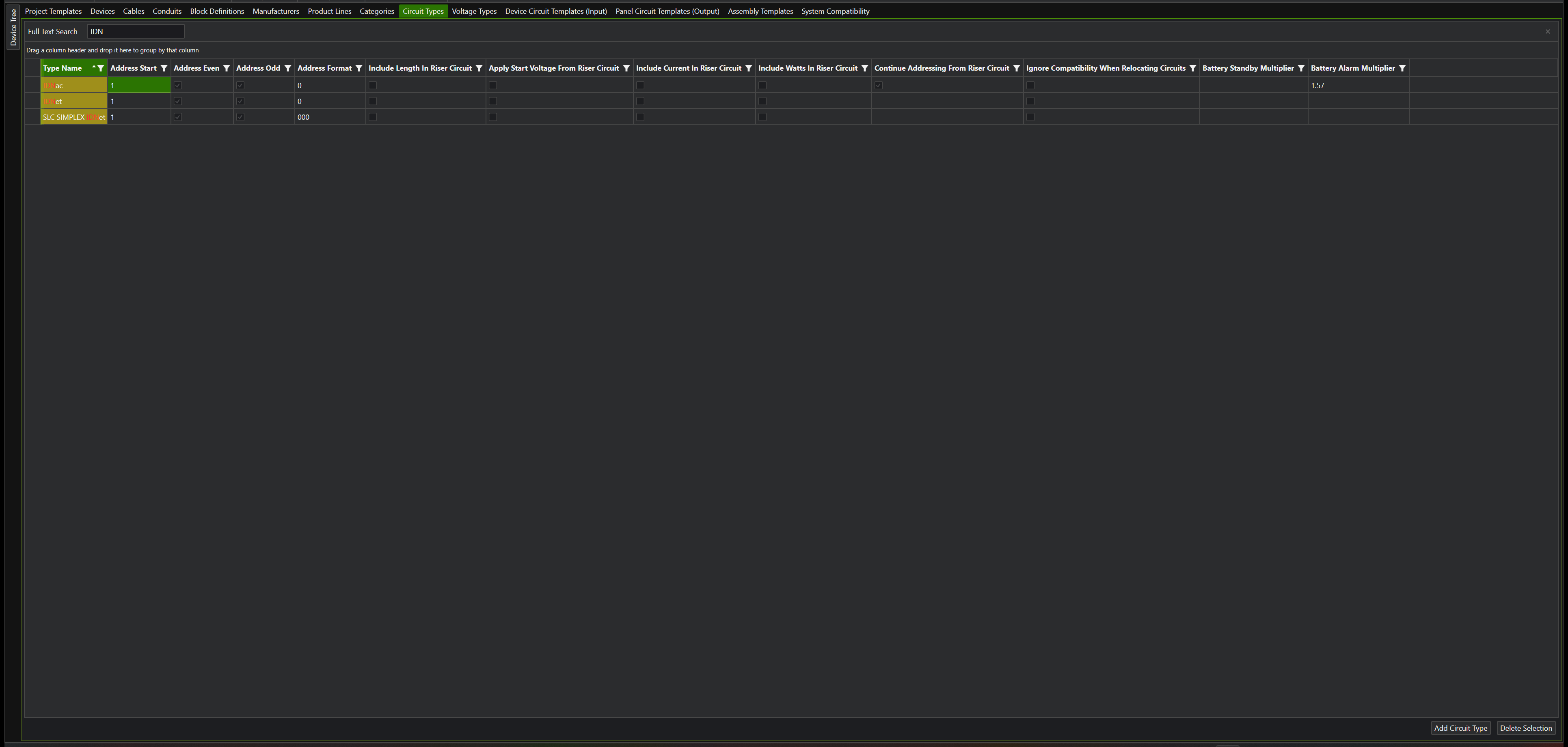
Per connection type. Open the Master Template Editor (or the project Device Editor for one project) and go to the Circuit Types pane. Two new columns, Battery Standby Multiplier and Battery Alarm Multiplier, hold the factor for every circuit of that type. The standard catalog sets
IDNacalarm to 1.57 andSLC AUTOCALL MXstandby and alarm to 2.496. Blank means 1.0.
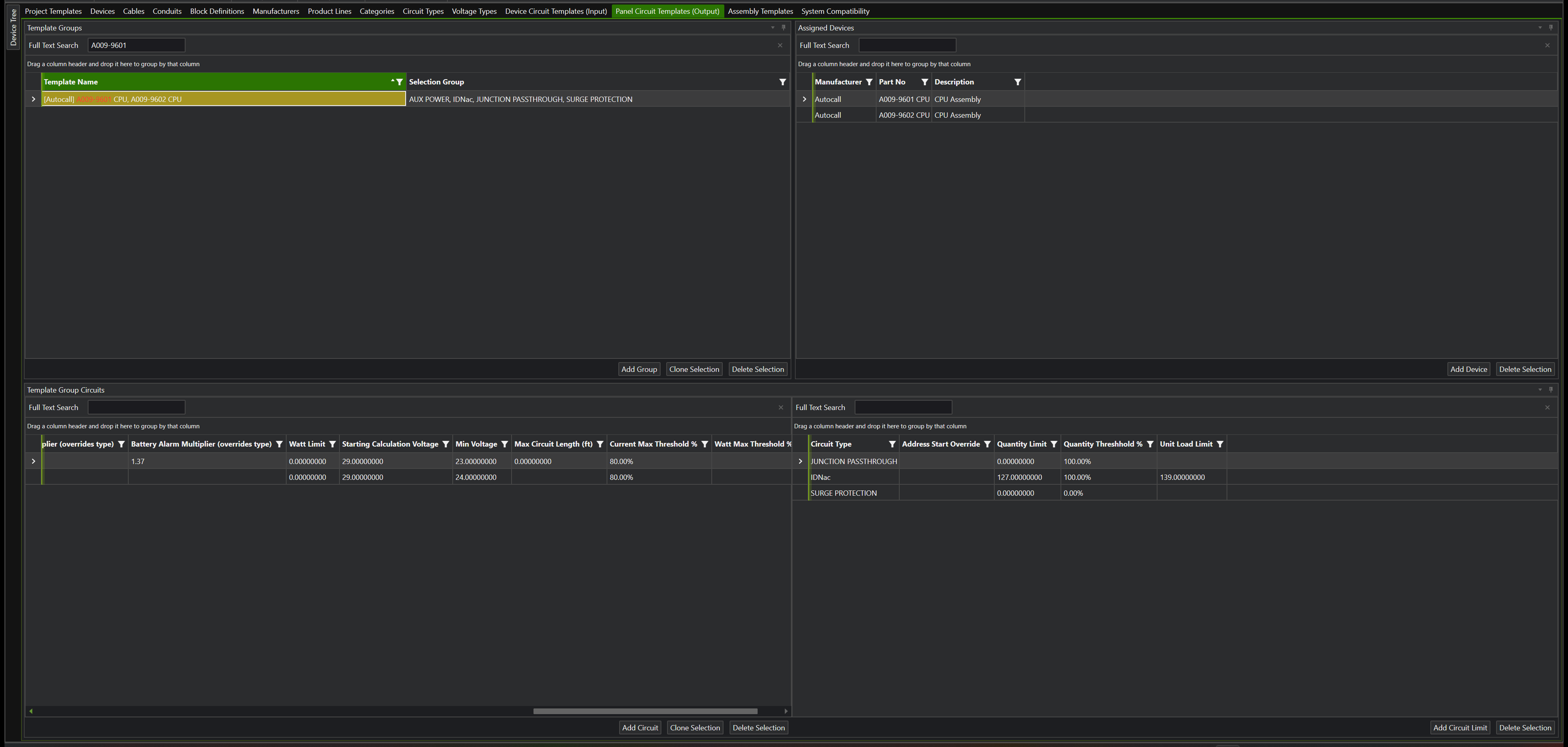
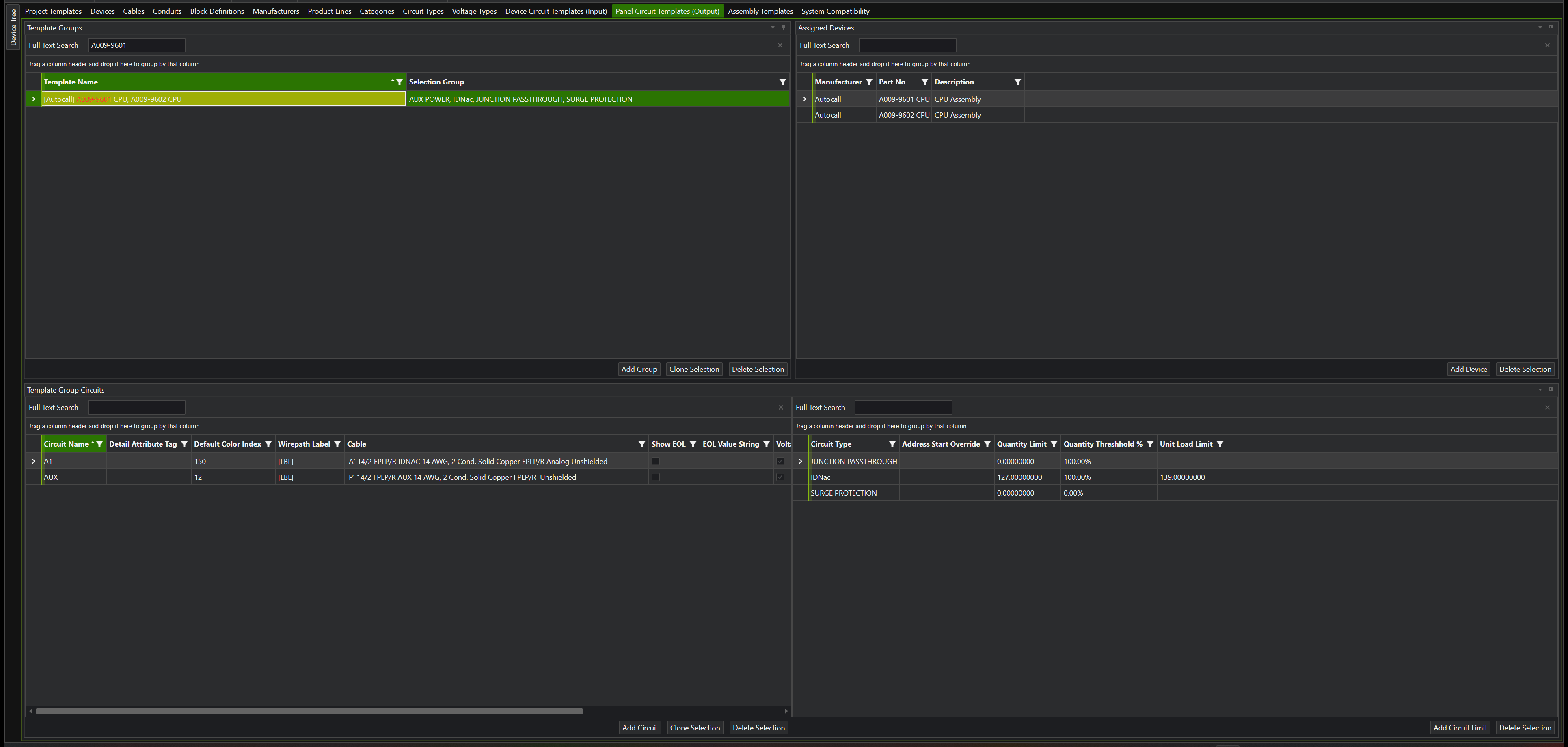
- Per circuit template, overriding the type. In the Panel Circuit Templates (Output) pane the same two columns appear as Battery Standby Multiplier (overrides type) and Battery Alarm Multiplier (overrides type). The standard catalog sets 1.37 on the IDNAC output of the two repeaters. Blank means use the type's value.
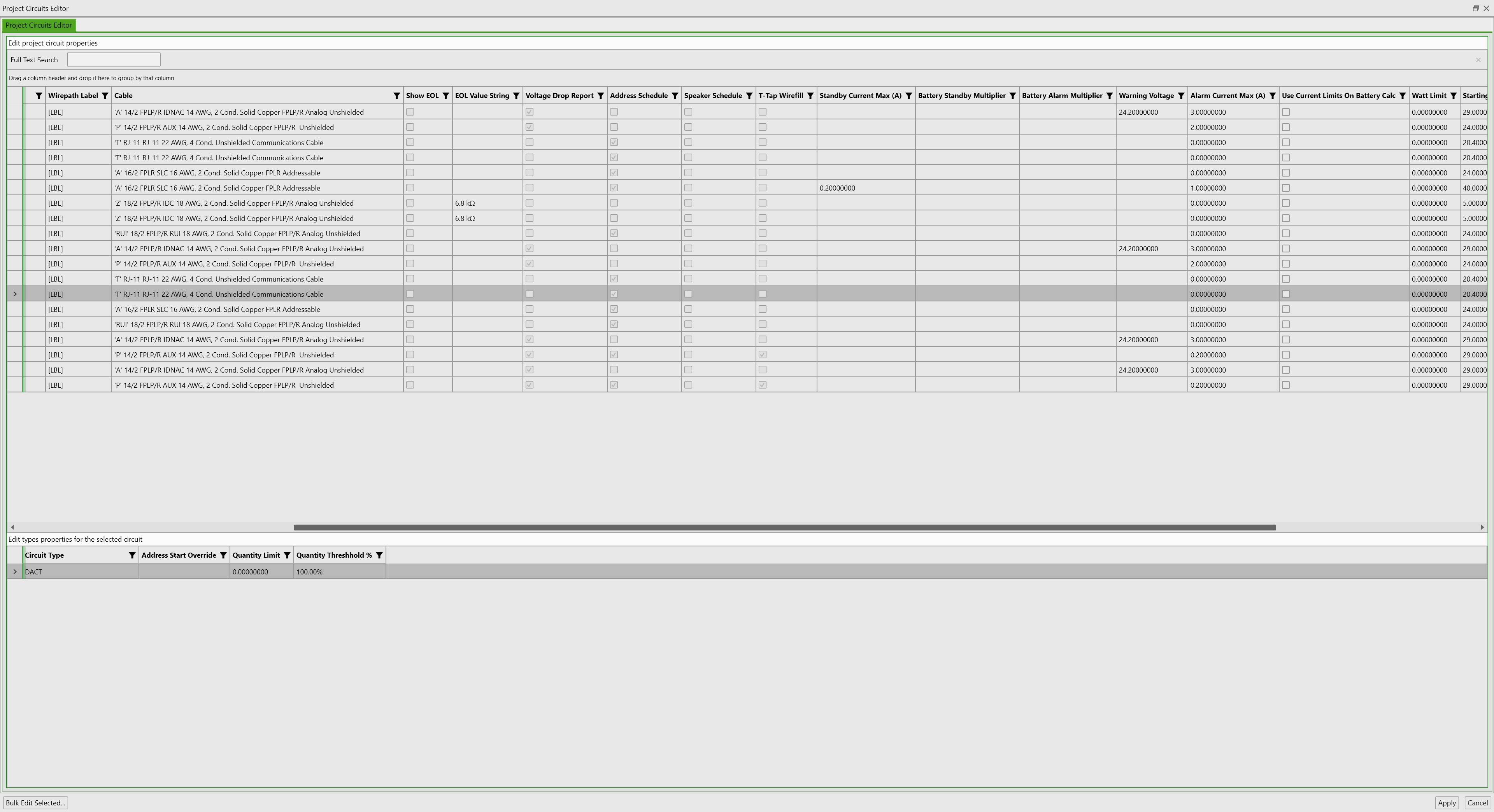
- Per circuit, overriding both. The Project Circuits Editor has the same two columns, Battery Standby Multiplier and Battery Alarm Multiplier, for one placed circuit. A value there wins over the template's and the type's for that circuit only; blank means inherit. Use it when one repeater section needs a different factor, or set 1 to switch the boost off on a circuit.
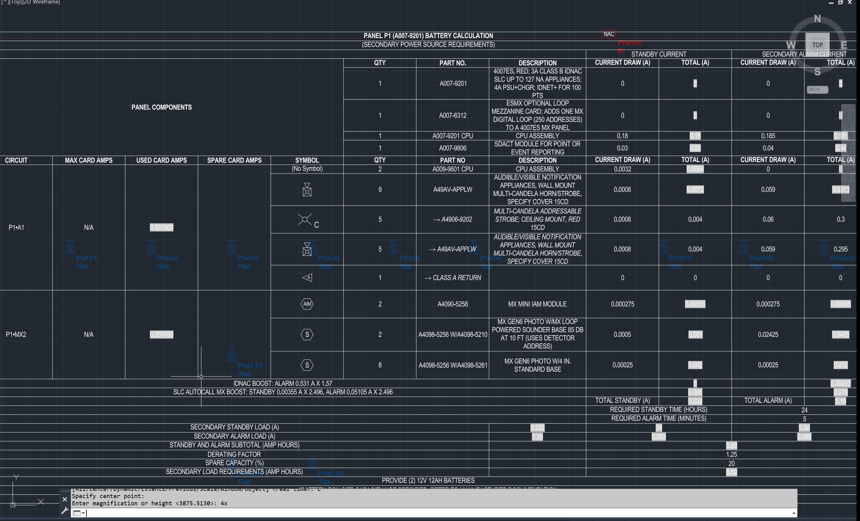
On the Battery Calculation report and the Panel Summary the boost prints as its own line, for example IDNAC BOOST: alarm 0.708 A x 1.57, so a FireCAD report can be reconciled with an FQQ printout line for line.
Spare capacity
Spare Capacity is a new project setting (default 0), next to the derating factor on the Reports tab of Options and in the Battery Sizing (NFPA 72) group of the battery report's Report Settings dialog. The battery calculation applies it on top of the derating factor: required AH = AH x derating x (1 + spare). It prints as SPARE CAPACITY (20%) when non-zero.
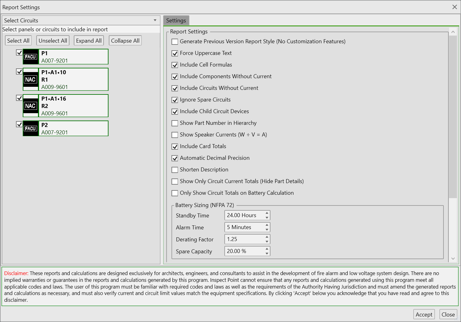
The Design Assistant has its own Spare circuit and battery capacity (%) preference on the Design Assistant tab of Options (default 20), which is the margin it keeps when it sizes circuits and batteries for you. The two are separate on purpose: the report prints what the project setting says, the assistant designs to its own margin.
The Design Assistant's battery check now reads standby hours, alarm minutes, derating and spare capacity from the project settings, so it sizes the same battery the report does. Previously it used fixed values of 24 hours, 5 minutes and 1.2.
Repeater batteries
A009-9601 and A009-9602 generate their own battery calculation with the FQQ battery sets (6.2, 10, 12.7, 18 and 25 AH; the cabinet holds up to 12.7 AH). Devices on the repeater's outputs load the repeater's batteries, not the panel's, and carry the 1.37 boost.
See also the Battery Calculation user guide.
Unit loads
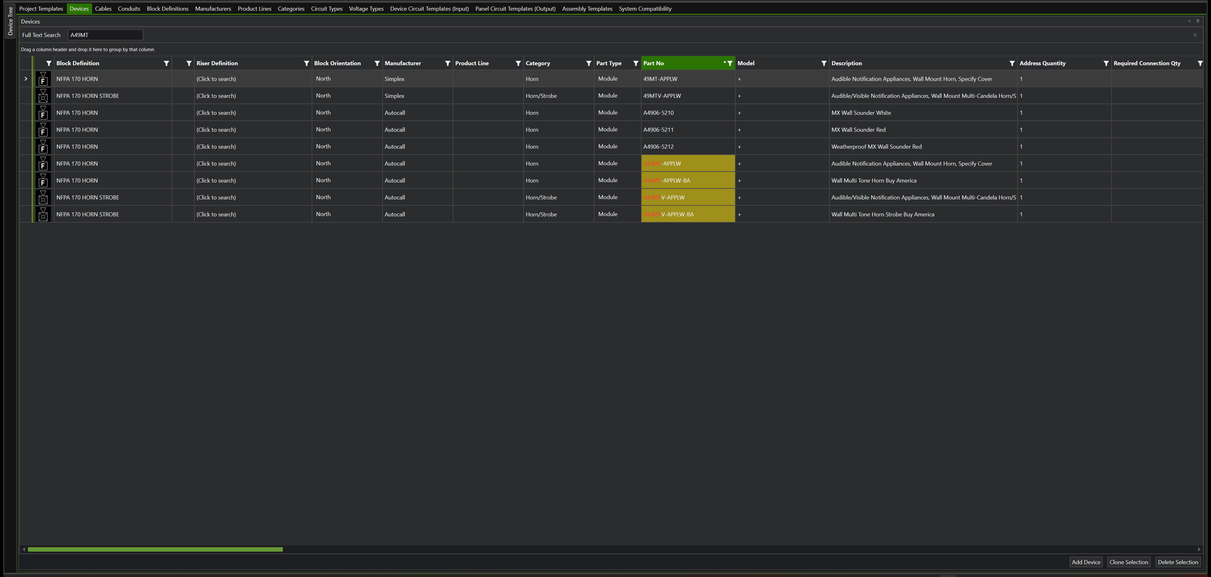
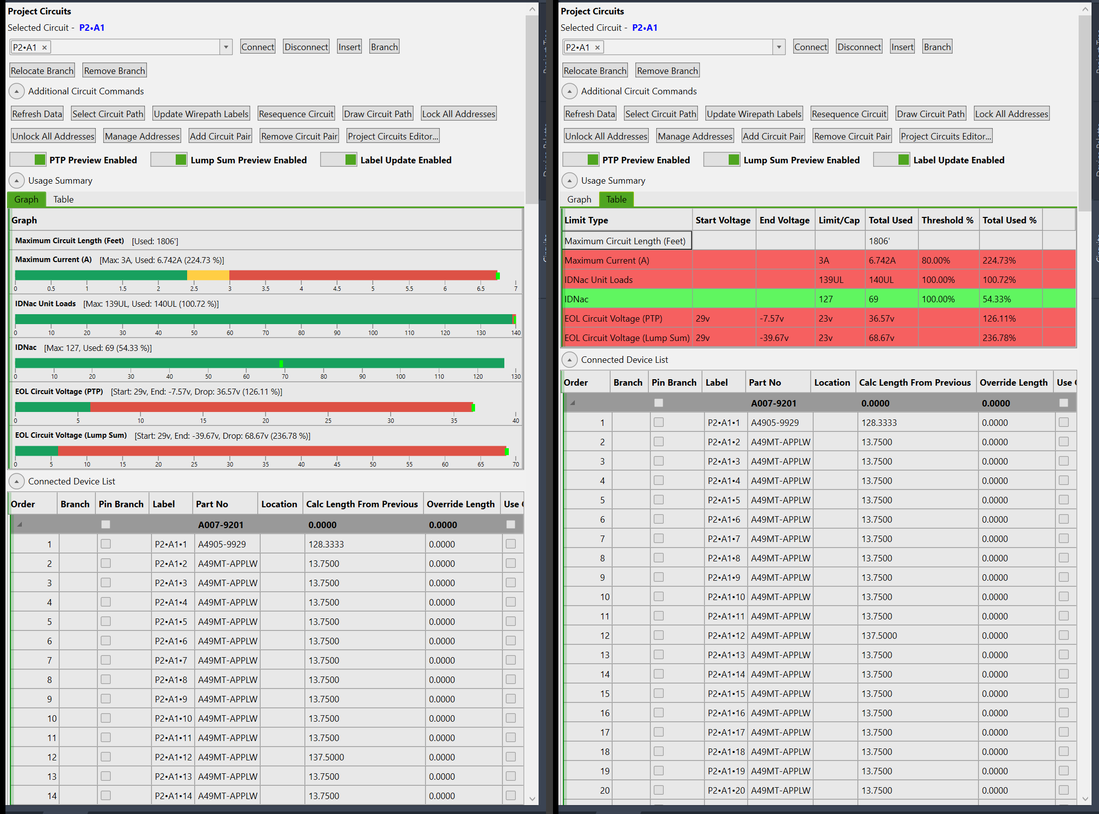
An IDNAC channel is limited to 139 unit loads and an IDNet loop to 250, separately from the 127 / 250 address limits. Most appliances are 1 unit load; multi-tone horns and horn/strobes (A49MT, A49MTV, 49MT, 49MTV families) are 2; the TrueAlert Isolator+ (A4905-9929) and the IDNAC repeaters are 4. A channel of 70 multi-tone horn/strobes passes the address count and fails the unit-load count, exactly as FQQ reports it.
Where the values live:
- Unit Loads column in the Devices pane of the Master Template Editor and the project Device Editor. Blank means 1.
- Unit Load Limit column on the circuit limit rows of the Panel Circuit Templates (Output) pane, next to the address Quantity Limit. Blank means no limit.
Where you see the result:
- The Project Circuits palette's live limit display gains a row such as
IDNac Unit Loads 140 of 139 UL, directly under the address row, so a channel can be green on addresses and red on unit loads. - The Design Assistant precheck reports
Unit loads exceeded on P2:A1 [IDNac]: used 140 unit loads but maximum is 139alongside its address-count findings.
Repeater sections count separately. Addresses continue through an IDNAC repeater, so a channel's 127 includes the devices on its repeaters' outputs. Unit loads do not: each repeater output has its own 139, and the feeding channel counts only the repeater itself, at 4 unit loads. This matches FQQ, which totals unit loads per repeater section. On the Autocall test project, panel channel P1/A1 reads 21 of 127 addresses (its own 11 plus 5 behind each repeater) and 17 of 139 unit loads (9 appliances plus 2 repeaters at 4).
Projects created before this update get the unit-load limits on their existing circuits the first time they are loaded or validated. Devices do not need to be re-placed.
Addressing on IDNAC repeaters
The repeater's outputs now continue the channel's address pool: a device on a repeater output takes the next free address from 1 to 127 on the parent channel, as FQQ assigns it, instead of restarting at 1. The channel's address total counts the repeater-output devices toward its 127.
Automatic addressing also fills gaps left by locked addresses (FQQ's "next free" mode) instead of continuing past the highest locked number.
IDNAC design checks
The Design Assistant precheck now runs the channel checks FQQ makes on an IDNAC design. Each one reads its limit from the catalog and does nothing where the limit is blank, so other manufacturers' circuits are not affected.
| Check | Limit (standard catalog) | Where the limit lives |
|---|---|---|
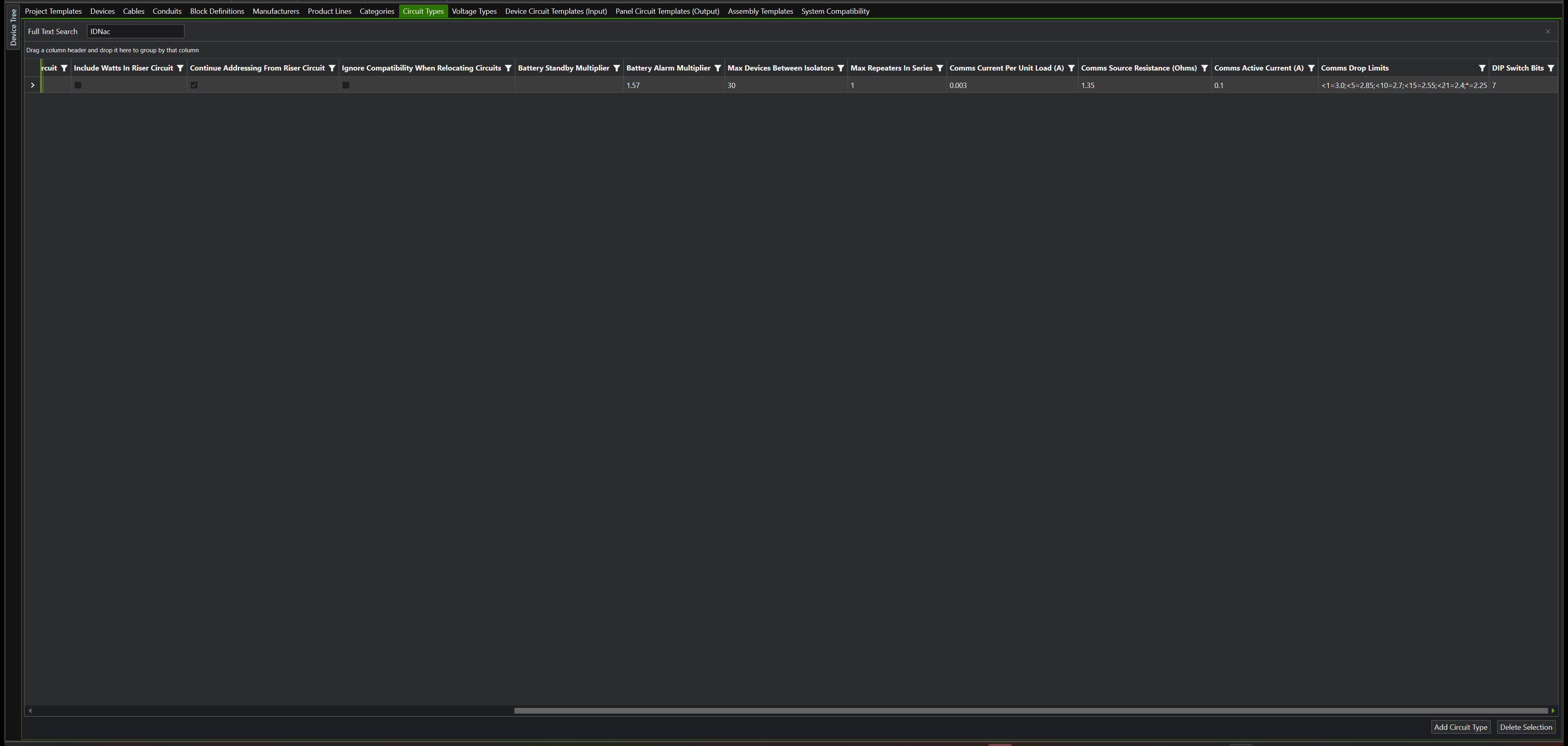
| Devices between isolators | 30 |
Max Devices Between Isolators on the IDNac row of the Circuit Types pane. Isolators are the parts whose Channel Role is ISOLATOR (A4905-9929, A4905-9849 and the Simplex equivalents). |
| Wire from the source to any device | 4,000 ft | Max Branch Length (ft) on the IDNAC circuit templates. The whole channel is also held to 10,000 ft through the existing maximum circuit length. |
| Repeaters in series | 1 (a repeater may not be fed from another repeater's output) |
Max Repeaters In Series on the IDNac circuit type. Repeaters are the parts whose Channel Role is REPEATER (A009-9601, A009-9602). |
| Repeaters and adapter modules per channel | 5 repeaters; 2 A4905-9816 adapters with a 4007ES, otherwise 4 |
Channel Caps on the IDNAC circuit templates, for example REPEATER=5;ADAPTER=2. Counted across the channel's repeater sections. |
| Communications voltage drop | 3.0 V with no speakers, down to 2.25 V with 21 or more | The Comms columns on the IDNac circuit type: 3 mA per unit load, 1.35 ohm source, 0.1 A active current, and the speaker-count table. |
A finding names the circuit, the device where the limit is reached and the value against the limit, for example P1:A1: 31 devices between isolators, more than the 30 allowed. These are Design Assistant findings; the Project Circuits palette's live limit display does not show them.
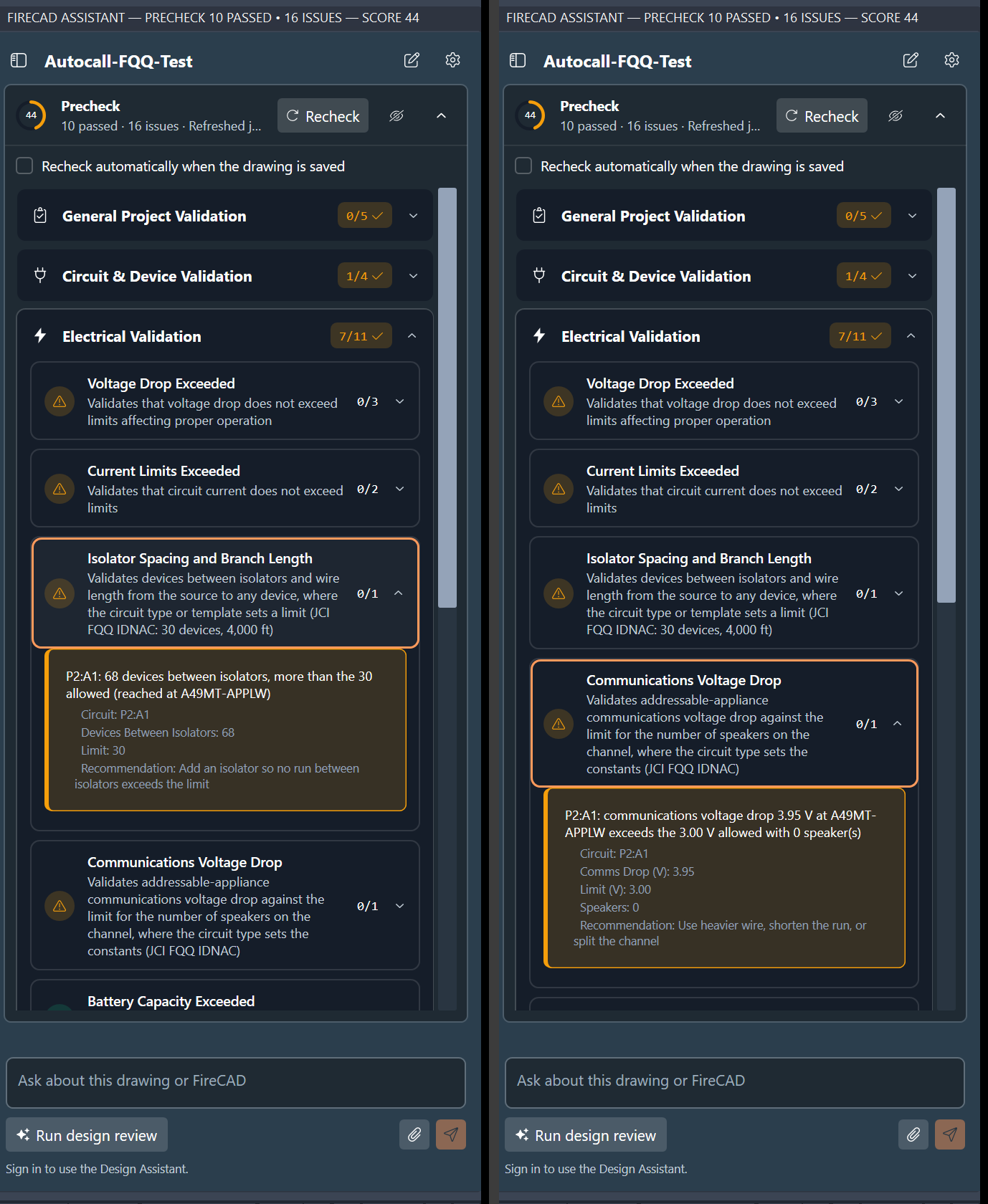
The limits on the IDNac circuit type reach an existing project the next time you run Update Project with the Autocall or Simplex template.
Warning voltage
FQQ marks an IDNAC appliance below 24.2 V as a warning and below 23 V as an error. Circuit templates and circuits now carry an optional Warning Voltage next to the minimum voltage: in the Panel Circuit Templates (Output) pane of the Master Template Editor, and in the Project Circuits Editor for one circuit. The standard catalog sets 24.2 V on the IDNAC templates that start at 29 V.
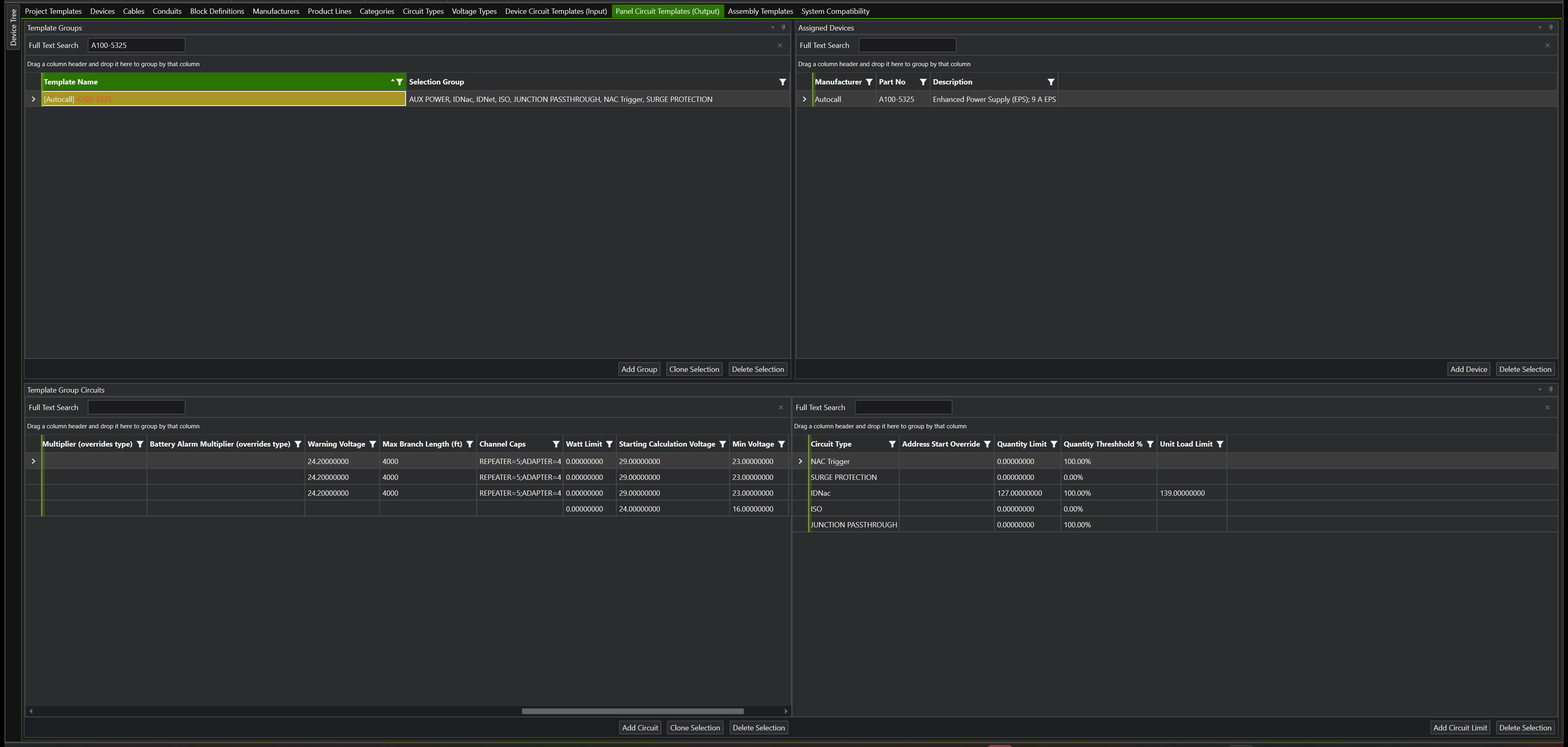
A circuit already placed in a project keeps the values it was given when it was connected, so circuits drawn before this release have no warning level until you set one. Enter it in the Warning Voltage column of the Project Circuits Editor and click Apply:
When a circuit's end-of-line voltage falls between the two:
- the End of Line cell on the Point-to-Point and Lump Sum reports and their summaries is amber instead of green (yellow in a table placed on the drawing);
- the Design Assistant reports a warning, not a failure.
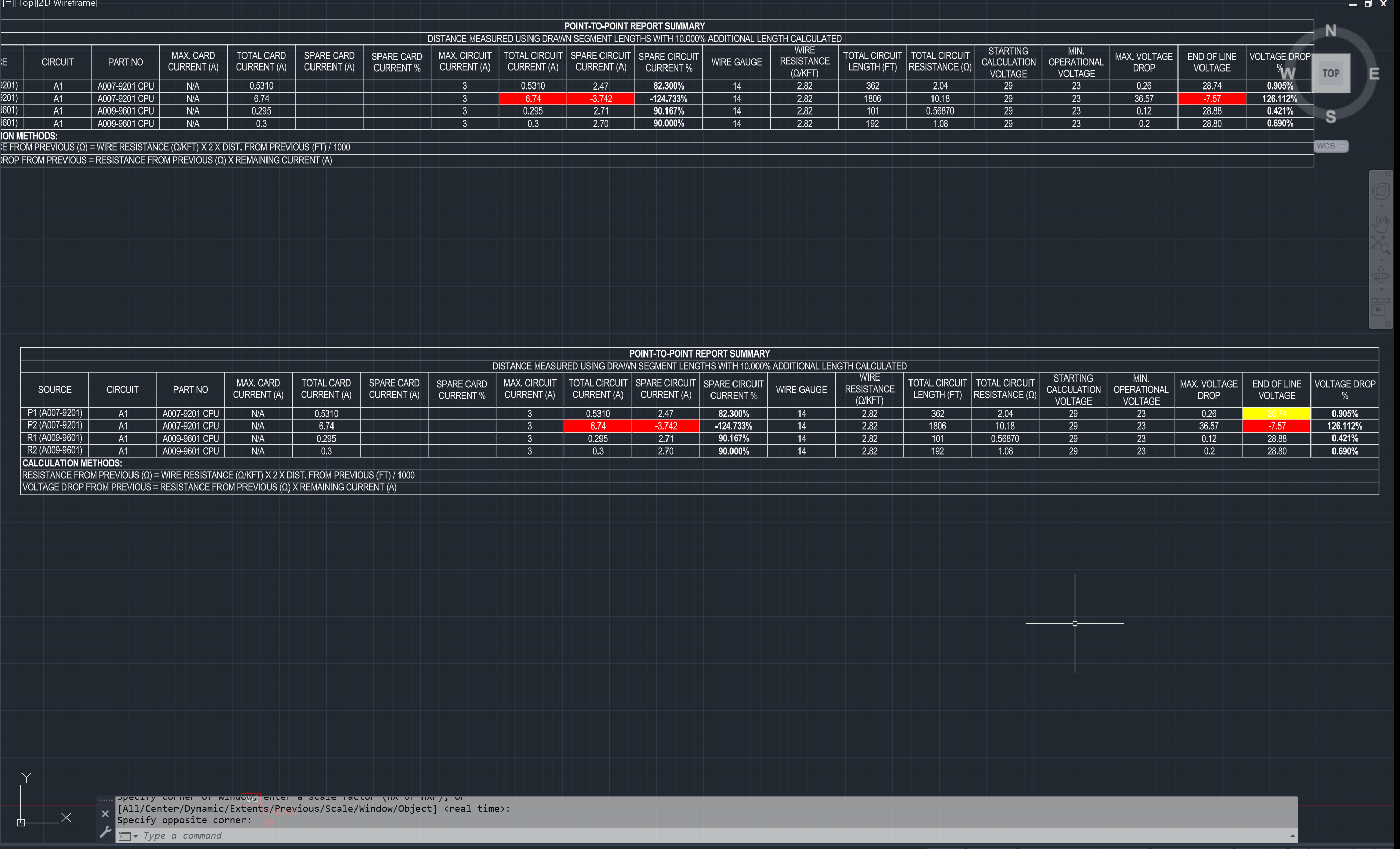
In this example P1/A1's warning level was raised to 28.8 V so that its 28.74 V end-of-line voltage falls in the warning band; P2/A1 is below the minimum and shows red.
Blank means no warning level, which is how every other circuit behaves.
DIP switch settings
IDNAC appliances are addressed with seven DIP switches. FireCAD can now print each device's address as switch positions, as FQQ does: switch n is bit n, so address 10 reads 0001010 (2,4 ON).
- Device Schedule: add the DIP Switches column in the report's column settings. A sheet whose devices have no switch settings leaves the column out. IDNAC circuit templates now go on the Device Schedule as well as the voltage drop reports. In an existing project, run Update Project with the Autocall or Simplex template, or tick Address Schedule for the circuit in the Project Circuits Editor.
-
Device labels: use the
[dip]token in Format Device Labels.
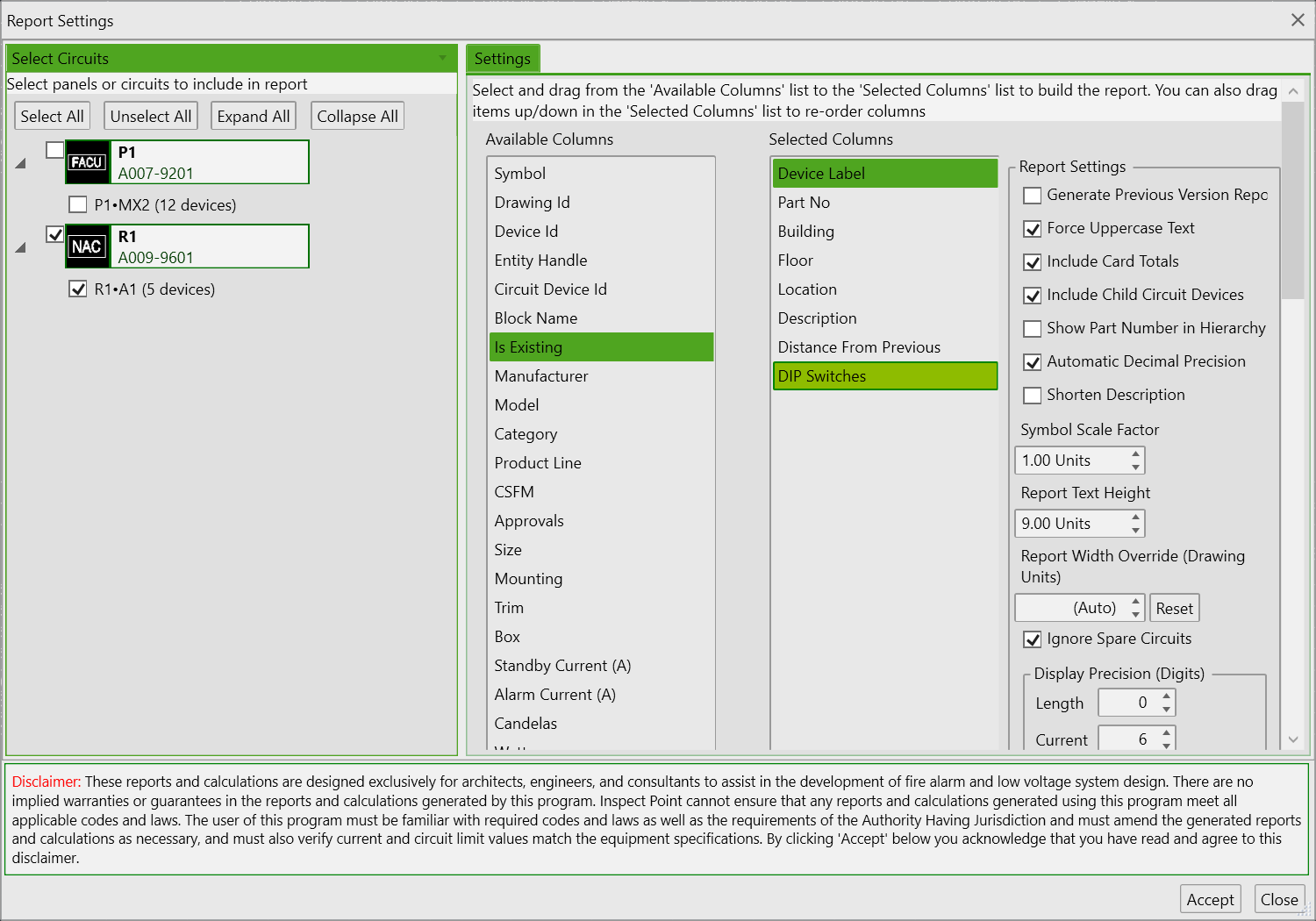
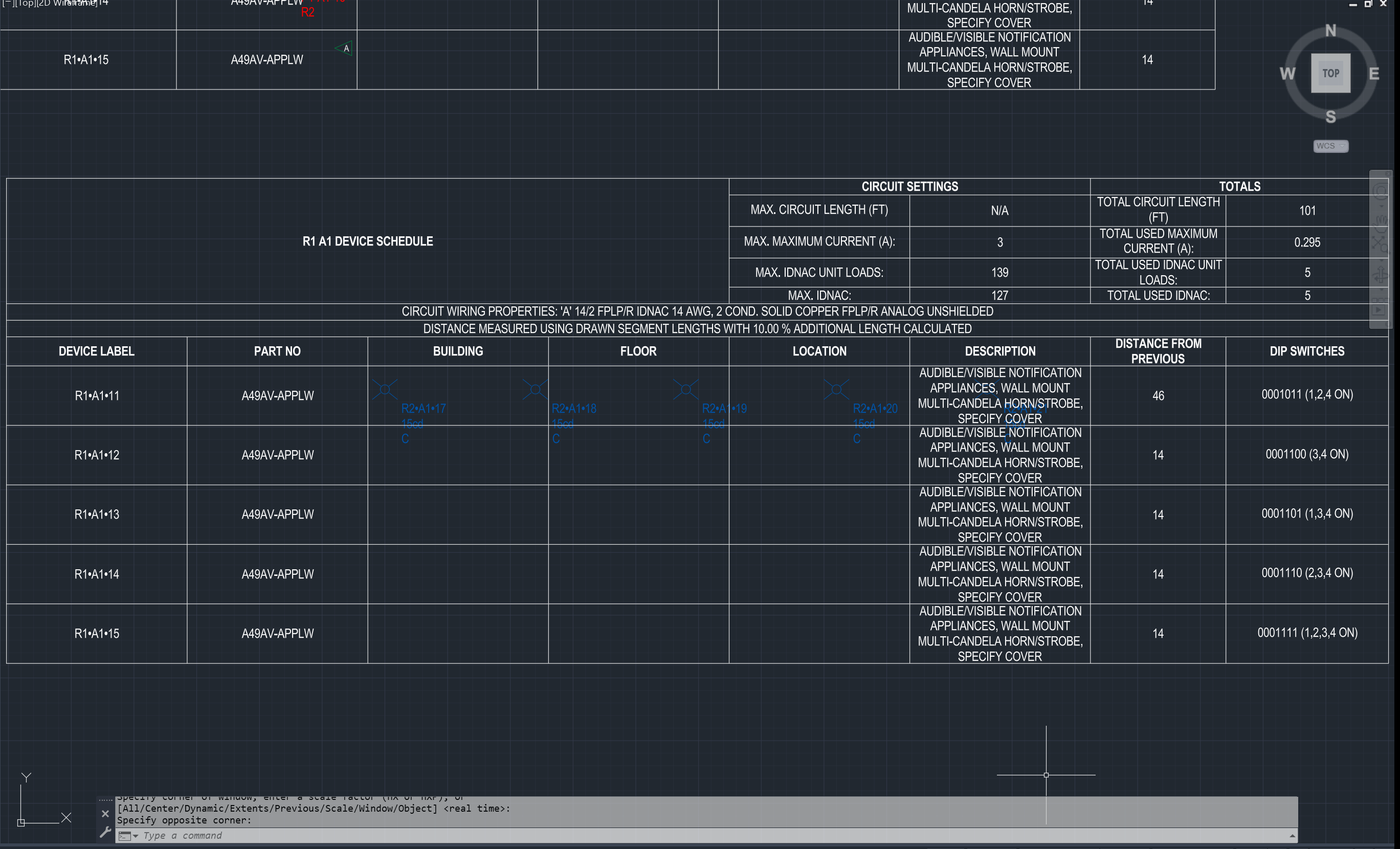
Only connection types with verified switch settings fill it in: the DIP Switch Bits column on the Circuit Types pane, 7 on IDNac. Everything else stays blank. A device with an overridden numeric address shows the switches for that address.
Branch numbers you can set
The Project Circuits palette's Branch column in the Connected Device tree is now editable, with a Pin Branch checkbox beside it and Pin Branch Number / Use Automatic Branch Number on the right-click menu. Type the number your drawing uses and the branch keeps it through Apply, reorder, validate, label refresh, save and reopen, and through branch commands elsewhere on the circuit. Branches you do not pin keep numbering themselves, and a new branch now takes the lowest free number rather than one above the highest, so a pinned 7 does not push the next branch to 8.
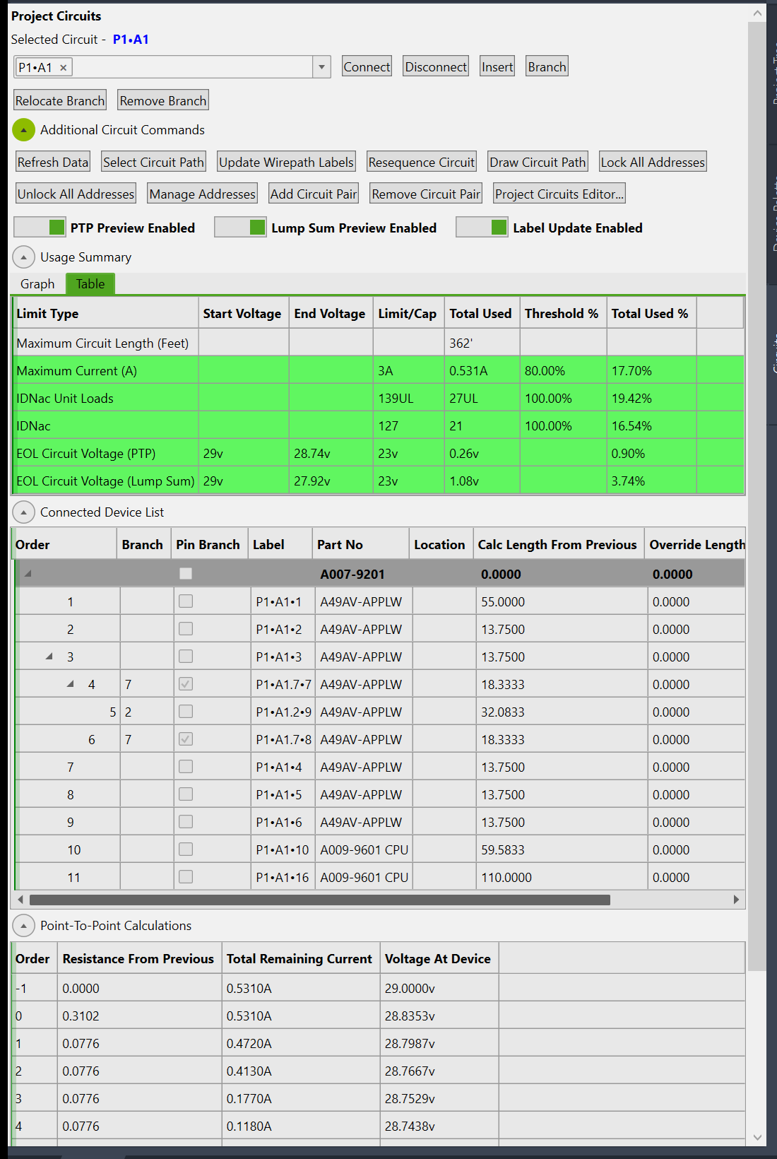
If a number is already pinned on another branch off the same device, FireCAD says so and leaves the branch as it was. The riser and the wire-path labels group on the pinned number.
Also fixed in this work
- Point-to-point voltage drop: a branch taken off a branch device now counts toward the current upstream of it (nested T-taps were understating drop).
- Class A circuits: voltage drop is checked from either end and the worse result is reported, as FQQ does.
- Panel Summary: standby and alarm current were being added together as "used amps"; they are now shown separately.
- Autocall annunciators (A4606-920x): standby current corrected from 0.045 A to 0.070 A (display active).
- Design Assistant alarm-current check: a panel's circuits were added up against every card; each card is now checked against its own circuits, so a panel with two NAC cards under capacity no longer reports an overload.
- The Add Card Current To Battery Calc column is hidden in the Master Template Editor. No calculation ever read it, so hiding it changes no result.
Catalog changes
The Autocall template grew from 701 parts to 997 and more than 300 existing parts were corrected against the FQQ workbook and the published datasheets. Where the datasheet and FQQ disagree, the datasheet value was kept. In the same pass:
- IDNAC circuit templates: 29 V start, 23 V minimum, 127 addresses, 139 unit loads, 3 A (or the card's own rating where it is lower, such as the 4009-9401 at 2.5 A).
- IDNet circuit templates: 250 unit loads.
-
A009-9601/A009-9602IDNAC repeaters: battery calculation on, FQQ battery sets, 4 unit loads, outputs continue the channel's addresses with the 1.37 boost. -
A4905-9929Isolator+: 4 unit loads, 3.2 mA standby. - Multi-tone appliances: 2 unit loads.
- November 8 additions: twelve 4120 / ES Net network display units, the A4017-RAMP-AR / -AP remote IDNAC amplifiers, eight ARAUD remote microphones, Isolator2 base, duct and abort-switch combinations, A190-9050 / -9051 AMZ modules, A4906 chime strobes and A49HFVH amber and blue strobes.
- The RAMP-NR / -NP remote amplifiers no longer include the optional A4017-NACEXP card by default.
- 4017 IDNet main boards include the 40 mA LED allowance; Simplex 4100-1326 to -1329 amplifiers use the datasheet battery currents.
- Six Generic 50 C cables, NAC and IDNAC at 12 / 16 / 18 AWG (1.77 / 4.50 / 7.14 ohm per 1,000 ft, FQQ's values).
- Channel roles set on the isolators, repeaters and A4905-9816 adapter modules, and the IDNAC design-check limits on the
IDNactype and templates. - California State Fire Marshal listing numbers added to 230 of the new parts.
Use Update Project to bring an existing project current with the standard catalog.
Custom databases
If FireCAD points at your own database, two different things happen.
Automatic: schema and default values
The first time this FireCAD version connects to your database it adds the new columns and fills their default values. This runs on any master database, yours included, and never overwrites a value that is already set.
| Table | New column | Default value written |
|---|---|---|
LimitTypes |
BatteryStandbyMultiplier, BatteryAlarmMultiplier
|
Alarm 1.57 on the type named IDNac; standby and alarm 2.496 on SLC AUTOCALL MX
|
CircuitTemplates |
BatteryStandbyMultiplier, BatteryAlarmMultiplier
|
Alarm 1.37 on IDNAC circuit templates whose group is linked to A009-9601 CPU or A009-9602 CPU
|
DeviceTable |
UnitLoads |
2 on part numbers beginning A49MT or 49MT; 4 on A4905-9929, 4905-9929 and part numbers beginning A009-9601 or A009-9602
|
CircuitLimitTemplates |
UnitLoadLimit |
139 on limits of type IDNac; 250 on IDNet and SLC SIMPLEX IDNet
|
LimitTypes |
MaxDevicesBetweenIsolators, MaxRepeatersInSeries, CommsUnitLoadAmps, CommsSourceOhms, CommsActiveAmps, CommsDropLimits, DipSwitchBits
|
On IDNac: 30, 1, 0.003, 1.35, 0.1, the FQQ speaker table, 7 |
CircuitTemplates |
WarnVoltage, MaxBranchLength, ChannelCaps
|
On IDNAC templates: 24.2 V where they start at 29 V with a 23 V minimum; 4,000 ft (and the existing maximum circuit length set to 10,000 ft); REPEATER=5;ADAPTER=2 on 4007ES templates, REPEATER=5;ADAPTER=4 otherwise |
DeviceTable |
ChannelRole |
REPEATER on A009-9601 / A009-9602; ISOLATOR on A4905-9929, A4905-9849 and the Simplex equivalents; ADAPTER on A4905-9816
|
Five project-level columns are also new (CircuitLimits.UnitLoadLimit, CircuitDevices.BranchNoLocked, Circuits.BatteryStandbyMultiplier / BatteryAlarmMultiplier and Circuits.WarnVoltage); they belong to the project database, which FireCAD creates and upgrades itself, so there is nothing to do for them.
The defaults are matched by name. If your IDNAC circuit type is named differently from IDNac, or your repeater CPU rows have a different part number, the defaults are not written and you set the values yourself in the Master Template Editor, in the columns shown above. That is a few cells, not a migration.
Not automatic: the Autocall parts and settings
These were applied to the standard catalog as data and do not reach a custom database on their own:
- the 296 new and the corrected Autocall parts, with their currents, blocks, circuit templates and CSFM listings, and the six 50 C cables;
- the IDNAC repeater configuration: battery calculation on, battery sizes
6.2,10,12.7,18,25, cabinet capacity 12.7, Enable Riser Connection Features on the repeater CPU, and Continue Addressing From Riser Circuit on theIDNaccircuit type (the setting that makes repeater outputs continue the channel's addresses); - IDNAC template values of 29 V / 23 V / 127 addresses / 3 A where yours differ;
- the A4606-920x standby correction.
You have two options:
-
Send us your database. Email your
.mdf(or give us access to your SQL Server) at support@cadgen.com. We merge the Autocall changes into it, keeping your own parts, blocks, mounting and other customizations, and return it. This is the usual route and takes a day. -
Apply what you need yourself. In the Master Template Editor: set the four columns in the table above if the names did not match; on the
IDNacrow of the Circuit Types pane tick Continue Addressing From Riser Circuit; on the repeater CPU rows tick Enable Riser Connection Features; on the repeater rows tick Generate Battery Calc and fill Battery Charging Capacities (CSV) with6.2,10,12.7,18,25and Battery Box Capacities (CSV) with12.7. New parts are easier to take from us than to build.
After either route, open each project and run Update Project so the project's copies of the templates pick up the new columns.
Related: How to connect to a local database, Opening the Device Editor, Riser circuit features and passthrough devices.
Reference values
| Quantity | Value | Source |
|---|---|---|
| IDNAC alarm boost at the panel | 1.57 | FQQ Battery Selection, 29 VDC boost |
| IDNAC alarm boost behind a repeater | 1.37 | FQQ Rep Batts
|
| ES-MX loop boost, standby and alarm | 2.496 | FQQ Battery Report E13 / E15 |
| IDNAC addresses per channel | 127 | FQQ IDNAC I36 |
| IDNAC unit loads per channel | 139 | FQQ IDNAC I37 |
| IDNet addresses and unit loads per loop | 250 / 250 | FQQ IDNet I27 / I28 |
| Unit loads: appliance / multi-tone / isolator / repeater | 1 / 2 / 4 / 4 | FQQ Appl Data M |
| IDNAC appliance standby | 0.8 mA per unit load | FQQ Battery Selection
|
| Repeater battery sets | 6.2, 10, 12.7, 18, 25 AH | FQQ Data AS2:AS7 |
| IDNAC warning / error voltage | 24.2 V / 23 V | FQQ FQECM Volts
|
| Devices between isolators | 30 | FQQ FQECM Dev-B-Iso
|
| Wire per branch / per channel | 4,000 ft / 10,000 ft | FQQ P2PMaxWirePerBranch / P2PMaxWireIDNAC
|
| Repeaters per channel / in series | 5 / 1 | FQQ IDNAC C48, FQECM Rep-Rep
|
| A4905-9816 adapters per channel | 2 with a 4007ES, otherwise 4 | FQQ P2PMaxDCAI
|
| Comms drop limit by speakers | none: 3.0 V; under 5: 2.85; under 10: 2.7; under 15: 2.55; under 21: 2.4; more: 2.25 | FQQ IDNAC P2P CA:CM |
| DIP switches per IDNAC appliance | 7, switch n = bit n | FQQ IDNAC P2P AT:BA |
| Wire resistance at 50 C, 12 / 16 / 18 AWG | 1.77 / 4.50 / 7.14 ohm per 1,000 ft | FQQ wire table |
FireCAD is the industry-leading AutoCAD add-in for fire alarm system design — from circuit layout to wire routing to code-compliant reports.
Learn more and get started at getfirecad.com →
Inspect Point Integration — Fire alarm system device lists and bill of materials can be pushed directly from FireCAD into Inspect Point, eliminating manual data entry and ensuring every device is ready for inspection scheduling and ongoing asset management.
Learn more here →