
Overview
Fire alarm change-outs and retrofits often land a group of addressable modules — monitor modules, relay modules, or a mix — inside a single terminal cabinet. Placing every module individually clutters the floor plan with symbols that all live at the same physical location.
This guide shows how to model the whole cabinet as one custom assembly part: a single symbol on the plan, the modules captured inside it as assembly contents, and a single SLC connection that consumes an address for every module in the cabinet. The drawing stays clean, and the addressing, device counts, and battery calculations still come out right.
The example builds a Generic TERM CAB (10) MONITOR MODULES — a terminal cabinet holding ten Notifier FMM-1 monitor modules. Substitute your own panel line's modules and counts.
How It Works
Three pieces make the cabinet behave correctly:
| Piece | Where | What it does |
|---|---|---|
| Assembly with contents | Assembly Templates tab | The modules live inside the cabinet as assembly parts — they show up in the assembly's bill of materials and battery calculations without being drawn on the plan |
| Address Quantity | Devices grid, on the cabinet part | The number of SLC points the cabinet consumes (10 in this example) |
| Apply Device Address Qty | The cabinet's SLC template row | Makes a single SLC connection consume the full Address Quantity instead of one address — the same mechanism combo devices like speaker/strobes use |
When the cabinet is placed and connected, the address sequencer assigns it a block of consecutive addresses and the label shows the range.
Prerequisites
- Access to your database through the Master Template Editor (the database utility included with FireCAD). If you work from the shared online database rather than your own copy, contact support and we will build the cabinet parts for you.
- The module counts for each cabinet configuration, and the module's standby/alarm current draw (from its datasheet).
Part 1: Clone a Terminal Cabinet Assembly
Start from an existing terminal cabinet that is already set up as an assembly — it carries the right category, plan and riser blocks, and connection slots, so the clone inherits all of it. The Generic FIRE ALARM TERMINAL CABINET is a good base.
- Open the Master Template Editor and connect to your database.
- On the Devices tab, type
terminal +cabinto Full Text Search. The+joins keywords, narrowing the list to rows matching both.
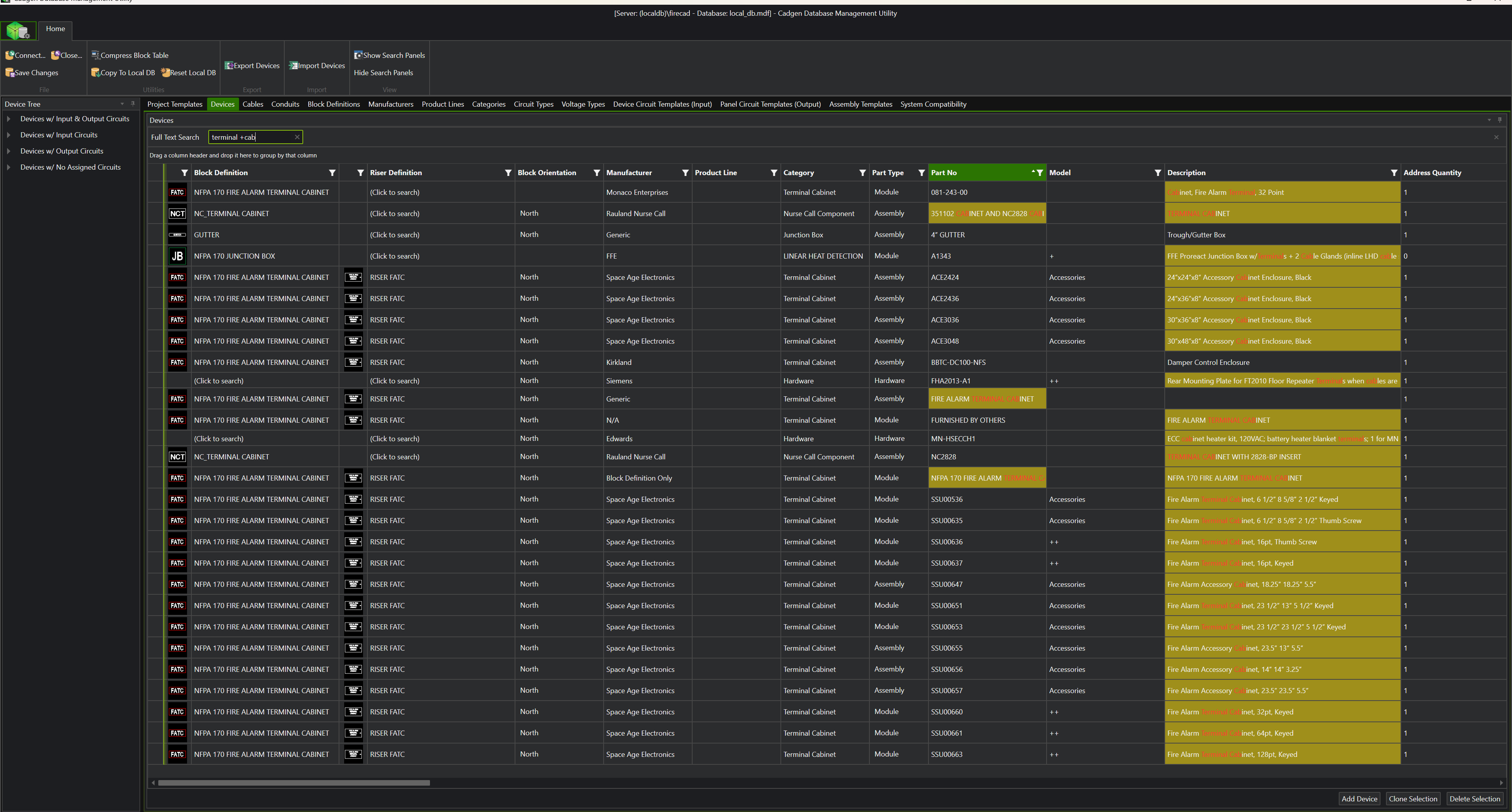
- Find the row with Part Type Assembly (Generic, FIRE ALARM TERMINAL CABINET), select it by its row header — the narrow cell at the far left of the row — and click Clone Selection. A new row appears with the part number suffixed "CLONED".
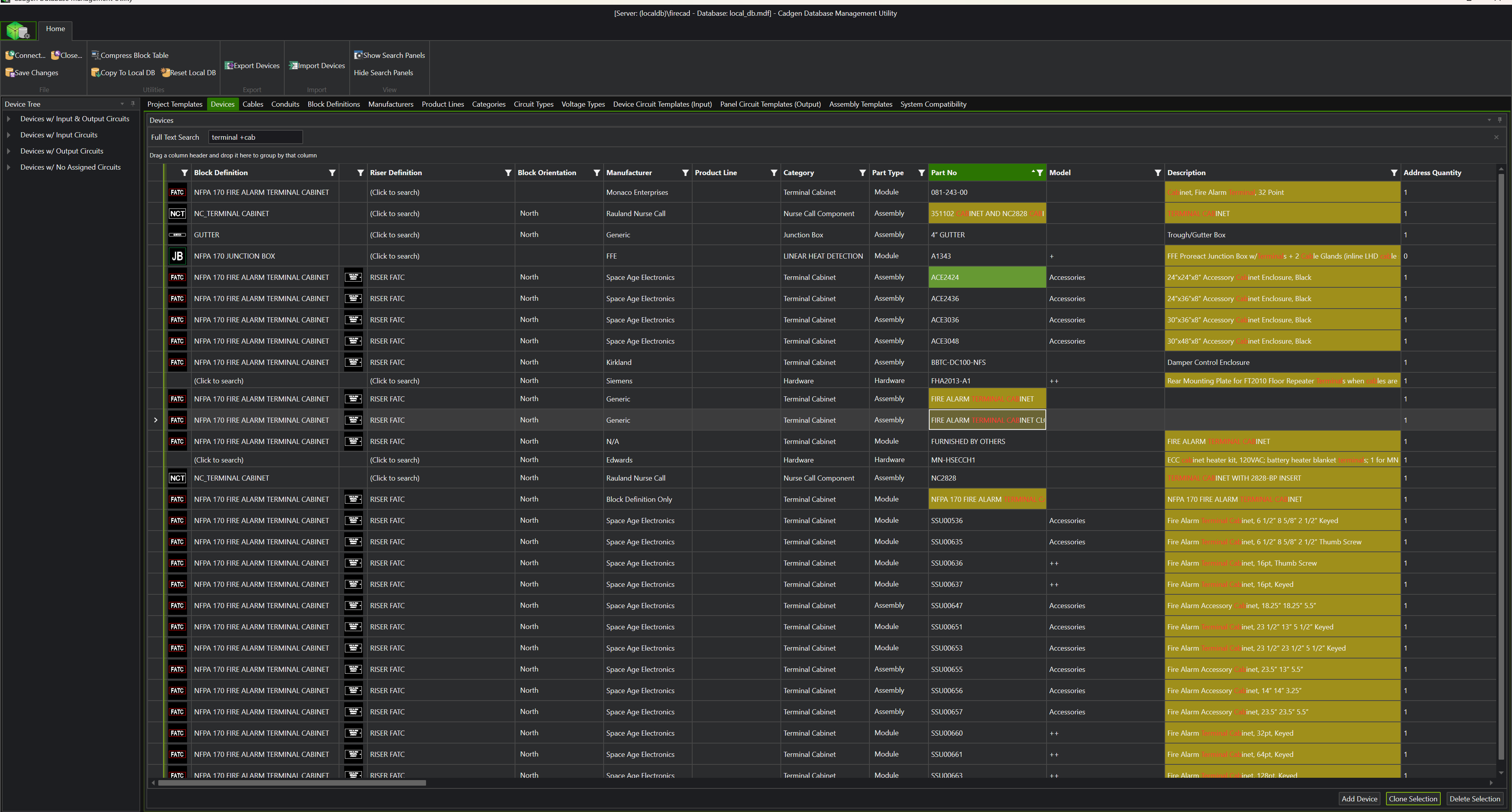
Selecting the row header matters: clicking an individual cell selects only that cell, and Clone Selection needs the whole row selected.
Part 2: Set the Cabinet's Fields
On the cloned row, set:
-
Part No — a name that reads well on the schedule, e.g.
TERM CAB (10) MONITOR MODULES -
Description — spell out the contents, e.g.
Terminal cabinet w/ (10) addressable monitor modules - Address Quantity — the number of SLC points in the cabinet (10 here)

Part 3: Put the Modules Inside
The cabinet's contents are configured on the Assembly Templates tab.
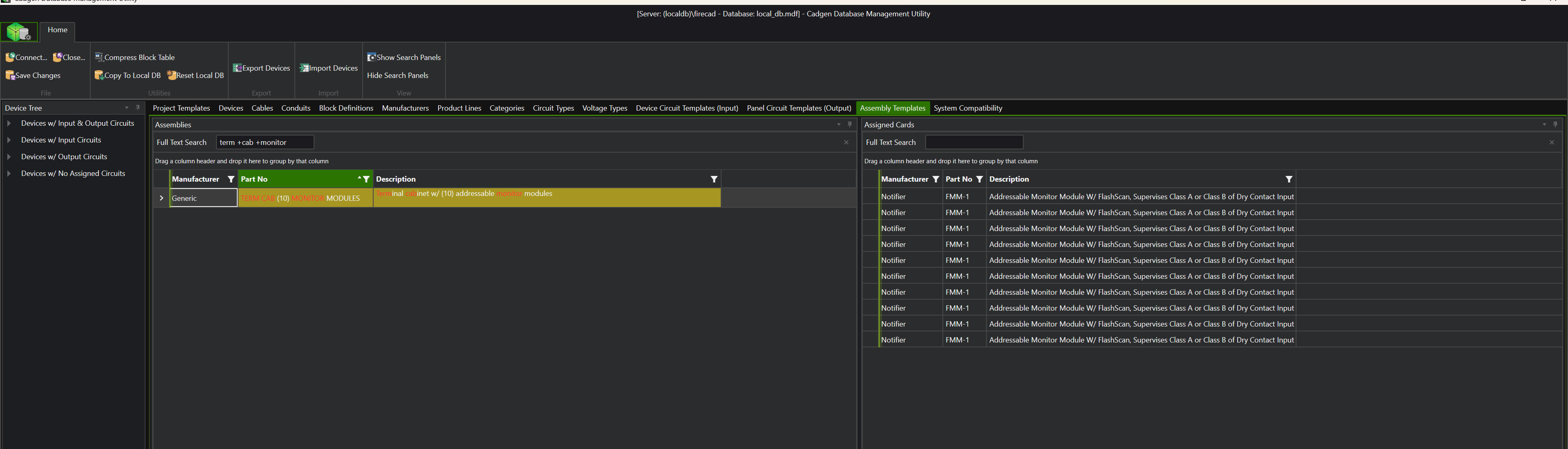
- Switch to Assembly Templates. Search for your new part in the Assemblies list and select it.
- Click Add Card (bottom right). The Select Devices dialog opens.
- Search for the module (e.g.
FMM-1), select its row, set Quantity to the module count, and click Add Devices.
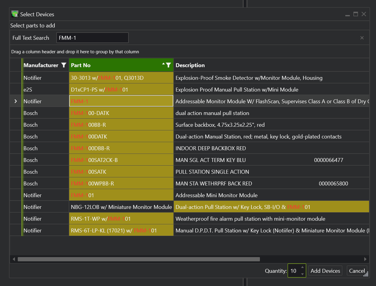
The modules now appear in the Assigned Cards list — ten FMM-1 rows inside the cabinet. Every placed instance of the cabinet includes these as its default contents.
Part 4: Give the Cabinet Its SLC Template
The clone inherits the source cabinet's connection templates. On the Generic terminal cabinet those are twenty general-purpose JUNCTION PASSTHROUGH slots — useful for routing circuits through the cabinet, but they are shared groups with other parts, they carry no current draw, and they do not apply the address quantity. Leave them alone and give your cabinet its own SLC template:
- On the Device Circuit Templates (Input) tab, find the SLC template group your modules use (search the module's part number), select it, and click Clone Template.
- Rename the cloned group so it is clearly the cabinet's (e.g. append
- TERM CAB 10). - On the cloned group's SLC row, set:
- Reqd Standby Current — module standby current × module count
- Reqd Alarm Current — module alarm current × module count
- Apply Device Address Qty — checked. Without this, the cabinet takes one address no matter what Address Quantity says.
- Add your cabinet part to the cloned group's devices, and remove it from any inherited group you don't want offered at connect time.
- Click Save Changes.
Never edit the shared group you cloned from — its current values and flags apply to every part in it.
Part 5: Pull the Part into Your Project
In an existing project, run Update Project to pull the new part in — see Updating Your Project. New projects pick it up automatically.
Part 6: Place and Connect
- Place the cabinet symbol on the plan — one block, at the cabinet location.
- Run
ATVALIDATEto register it. - Connect the SLC to the cabinet once, like any device.
The address sequencer assigns the cabinet a block of consecutive addresses, the label shows the range, and the loop's point count and battery calc reflect all the modules inside.
Cabinet Size Variants
Make one part per configuration you actually use — TERM CAB (5) MONITOR MODULES, TERM CAB (6) RELAY MODULES, and so on. Each is a clone of your first cabinet with its own Address Quantity, contents, and template currents. Mixed cabinets work the same way: Address Quantity is the total point count, currents are the summed totals.
Notes and Limits
- Device schedule — the cabinet appears as one line item; put the module count in the part number and description so the schedule reads clearly. The modules themselves are captured as the assembly's contents.
- Field wiring from the modules — the cabinet's inherited junction-passthrough slots let you land or pass other circuits (monitored zones, relay outputs) at the cabinet if you also draw that side of the wiring.
Troubleshooting
| Symptom | Cause |
|---|---|
| Cabinet only consumes one address | Apply Device Address Qty is not checked on the template row the cabinet actually connected through |
| Loop shows the wrong standby/alarm load | Currents on the cabinet's template row are still zero or single-module values — set them to the totals |
| Label shows one address instead of a range | Check the label format — see Formatting Device Labels for address display options |
| Part missing in an existing project | Run Update Project and select the manufacturer template that contains the cabinet part |
FireCAD is the industry-leading AutoCAD add-in for fire alarm system design — from circuit layout to wire routing to code-compliant reports.
Learn more and get started at getfirecad.com →
Inspect Point Integration — Fire alarm system device lists and bill of materials can be pushed directly from FireCAD into Inspect Point, eliminating manual data entry and ensuring every device is ready for inspection scheduling and ongoing asset management.
Learn more here →