
Preview: this page describes the next FireCAD release, planned for December 1, and the beta available now. For the current release, see Battery Calculation - User Guide.
Overview
The Battery Calculation feature helps you determine the correct backup battery size needed for fire alarm control panels (FACPs) and other fire safety equipment. The system automatically calculates power requirements based on your panel configuration and connected devices, then recommends appropriate battery sizes that meet code requirements.
What Does It Calculate?
The battery calculation determines:
- Standby Current: How much power the system draws during normal operation
- Alarm Current: How much power the system draws during a fire alarm event
- Required Amp-Hours: Total battery capacity needed to power the system for the required standby and alarm periods
- Battery Size Recommendation: Smallest battery that meets your requirements
- Power Supply Capacity: Whether your power supply can handle the alarm load
- Battery Boost: Extra current drawn from the battery by circuits that run above 24 V (Autocall / Simplex IDNAC and ES-MX loop)
Key Concepts
Standby vs. Alarm Current
- Standby Current: The electrical current (amps) your system draws while monitoring but not in alarm. This is typically lower because devices like strobes and horns are off.
- Alarm Current: The electrical current (amps) your system draws during an active alarm. This is typically higher because notification devices (strobes, horns, speakers) are activated.
Amp-Hours (AH)
Amp-hours measure battery capacity. It's calculated as:
Amp-Hours = Current (amps) × Time (hours)
Example: If your system draws 2 amps for 24 hours, you need at least 48 amp-hours of battery capacity.
Derating Factor
A safety multiplier (FireCAD default 1.25, or 25%) applied to your calculated battery requirement. This accounts for:
- Battery aging and capacity loss over time
- Temperature effects (batteries perform worse in cold conditions)
- Manufacturing tolerances
- Safety margin for reliability
Spare Capacity
An optional percentage applied on top of the derating factor, for specifications that call for spare battery capacity (for example 20%). It is 0 unless you set it.
Battery Boost
Device currents are rated at 24 V. A circuit that runs at a higher voltage draws more from the battery than its devices' stated current: an Autocall / Simplex IDNAC boosts to 29 V in alarm, and the ES-MX loop runs at 40 V. FireCAD multiplies the current of devices on those circuits and shows the extra current as its own line. See Battery Boost Multipliers below.
User-Configurable Options
Project Battery Settings
These settings apply to every battery calculation in the project. Each one appears in two places, and both edit the same value:
- Options > Reports > Battery calculation (NFPA 72)
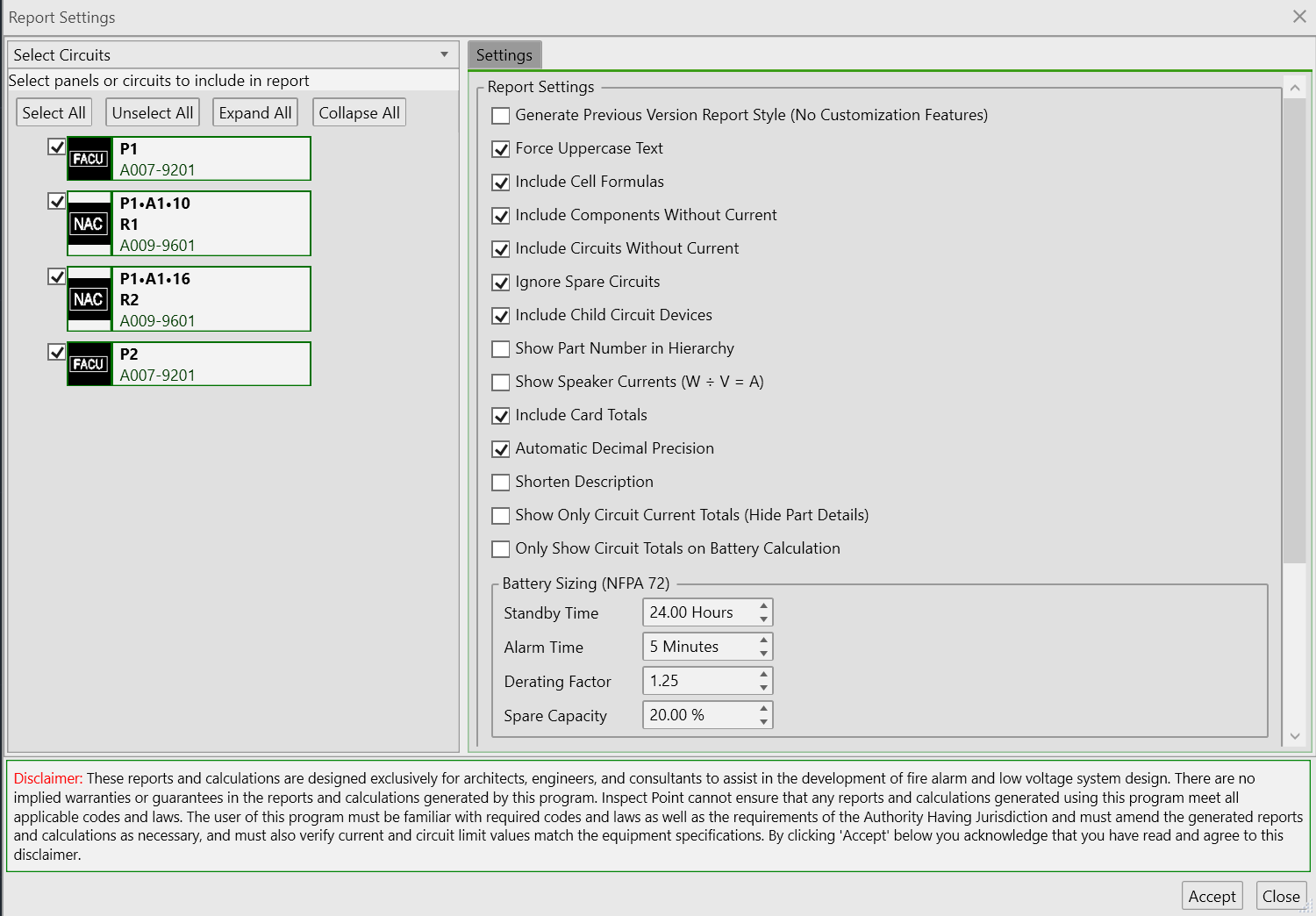
- The report window's Settings pane, Battery Sizing (NFPA 72) group
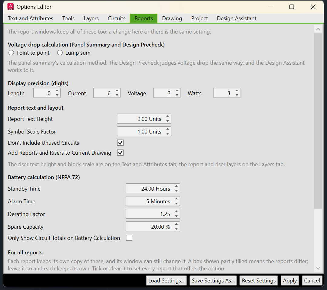
1. Standby Time (Hours)
Default: 24 hours
How long your system must operate on battery power during normal standby conditions.
- What it means: Most fire codes require 24 hours of standby operation
- When to change: Some jurisdictions require 60 hours or more for certain occupancies
- Example: If set to 24 hours and your standby current is 1.5 amps, you need 1.5A × 24hrs = 36 amp-hours for standby
2. Alarm Time (Minutes)
Default: 5 minutes. A voice project uses at least 15 minutes automatically.
How long your system must operate in full alarm condition on battery power.
- What it means: NFPA 72 requires 5 minutes of alarm for most systems and 15 minutes for an emergency voice/alarm communication system
- Voice projects: When the project has speaker circuits (any circuit that appears on the decibel loss report and has at least one device), FireCAD uses the larger of your setting and 15 minutes for every panel in the project. Your saved setting is not changed, and the report's REQUIRED ALARM TIME (MINUTES) line shows the time actually used.
- When to change: Set a higher value if your jurisdiction requires it; a higher setting always wins
- Example: If set to 5 minutes and your alarm current is 4 amps, you need 4A × (5/60)hrs = 0.333 amp-hours for alarm
3. Derating Factor
Default: 1.25 (25% safety margin)
Multiplier applied to the calculated battery requirement to ensure adequate capacity over the battery's lifetime.
- What it means: Your final battery size will be 25% larger than the theoretical minimum
-
Common values:
-
1.25(25%) - Standard for most installations -
1.20(20%) - Minimum acceptable for most codes -
1.30(30%) - Conservative for harsh environments
-
- Why it matters: Batteries lose capacity as they age. A new 100AH battery might only provide 80AH after several years of service.
4. Spare Capacity (%)
Default: 0 (none)
Extra battery capacity on top of the derating factor: required AH = AH × derating × (1 + spare %).
- When to use: A specification or manufacturer design tool that requires spare battery capacity (for example, JCI's FQQ workbook)
- On the report: When above 0, a SPARE CAPACITY (%) line prints under DERATING FACTOR, and SECONDARY LOAD REQUIREMENTS (AMP HOURS) includes it. At 0 the line is not printed and the result is the same as before.
- Design Assistant: The assistant has its own spare capacity preference on the Design Assistant tab of Options. That is the margin it designs to; the report always uses this project setting.
5. Only Show Circuit Totals on Battery Calculation
On the Options Reports tab and in the report window's Settings pane. Controls the level of detail shown in the battery calculation report.
Unchecked: Shows every device with its individual current draw
Circuit: L1.NAC-1
  Strobe (Qty 4) - 0.150A each = 0.600A
  Horn (Qty 2) - 0.020A each = 0.040A
  Circuit Total: 0.640A
Checked (Compact): Shows only circuit totals
Circuit: L1.NAC-1
  Circuit Total: 0.640A
- When to use compact: For large projects with hundreds of devices where you only need summary information
Report Settings
These options are in the Report Settings group of the report window's Settings pane. Most users can leave them as they are.
| Option | What it does |
|---|---|
| Force Uppercase Text | Converts the report text to uppercase |
| Include Cell Formulas | Writes Excel formulas (for example =B10*C10) instead of fixed numbers, so you can try what-if changes in Excel |
| Include Components Without Current | Lists panel cards and modules even when they have no current values |
| Include Circuits Without Current | Lists circuits with no devices or zero current |
| Ignore Spare Circuits | Leaves out circuits with no connected devices |
| Include Child Circuit Devices | Includes devices on circuits fed through riser (passthrough) devices. See Hierarchical Circuit Support below |
| Show Part Number in Hierarchy | Shows the part number in the child-circuit hierarchy |
| Show Speaker Currents (W ÷ V = A) | Converts speaker wattage to alarm current using the circuit voltage |
| Include Card Totals | Adds the MAX / USED / SPARE CARD AMPS columns |
| Automatic Decimal Precision | Trims trailing digits. Amp-hours and battery sizes keep their decimals when it is off |
| Shorten Description | Uses the short device description |
| Show Only Circuit Current Totals (Hide Part Details) | Aggregates devices into one totals row per circuit |
The Display Precision (Digits) group sets the decimal places for length, current, voltage and watts.
Battery Boost Multipliers
A battery multiplier raises the current a circuit draws from the battery. It applies to the battery calculation and the Panel Summary only; it never changes voltage drop.
Standard Values
| Circuit | Standby | Alarm | Source |
|---|---|---|---|
Autocall / Simplex IDNAC (circuit type IDNac) |
1 | 1.57 | IDNAC boosts to 29 V in alarm |
| IDNAC output of an IDNAC repeater (A009-9601 / A009-9602) | 1 | 1.37 | Set on the repeater's circuit templates |
Autocall ES-MX loop (SLC AUTOCALL MX) |
2.496 | 2.496 | 40 V loop |
All other circuit types have no multiplier, so every other manufacturer's calculation is unchanged.
Where Multipliers Are Set
The most specific value wins, separately for standby and for alarm:
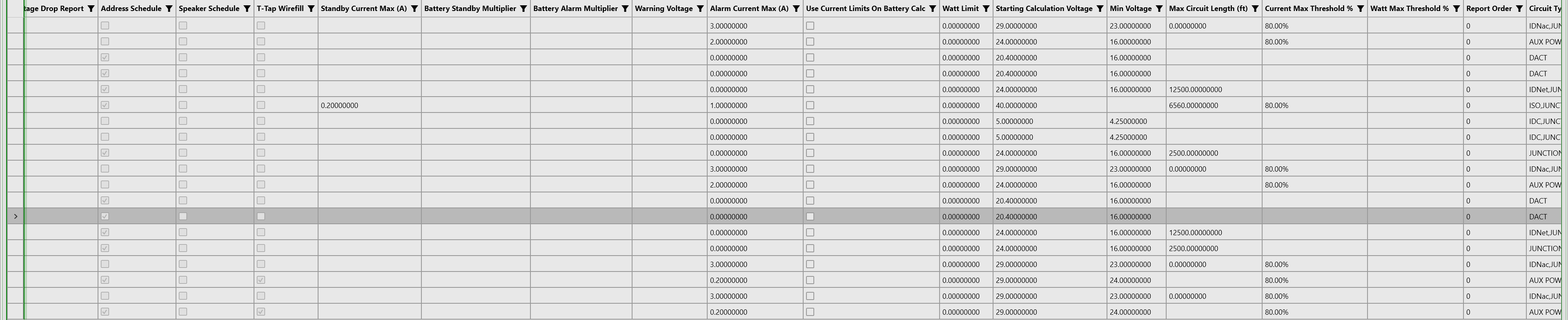
- Circuit type: Master Template Editor (or the project Device Editor), Circuit Types pane, columns Battery Standby Multiplier and Battery Alarm Multiplier. Blank means 1.
- Circuit template: Panel Circuit Templates (Output) pane, columns Battery Standby Multiplier (overrides type) and Battery Alarm Multiplier (overrides type). Blank means use the type's value.
- One placed circuit: Project Circuits Editor, columns Battery Standby Multiplier and Battery Alarm Multiplier. Blank means inherit. Enter 1 to switch the boost off on that circuit.
Important: A template or circuit value only applies to device connections whose circuit type already has a multiplier; it does not boost other devices that share the circuit. A value of 1 or less means no boost. Circuits counted at their power-limited circuit limit are not boosted, and child-circuit rows are not boosted twice.
How the Boost Appears on the Report
Each boosted circuit type gets one line after the circuits, for example:
IDNAC BOOST: alarm 0.708 A x 1.57 0.40356
The value is the extra current (0.708 × (1.57 - 1) = 0.404 A), added to TOTAL ALARM (A). With Include Cell Formulas on, the cell holds the formula 0.708*(1.57-1). An ES-MX loop line shows both standby and alarm, for example SLC AUTOCALL MX BOOST: standby 0.12 A x 2.496, alarm 0.15 A x 2.496.
Battery Calculation Method
Step-by-Step Calculation Process
The system performs calculations in this order:
Step 1: Calculate Standby Current
The system totals all standby current from:
Panel Components (cards installed in the panel chassis):
Component Current = Quantity × Device Standby Current
Circuit Devices (devices connected to panel circuits):
Device Current = Quantity × Device Standby Current
Total Standby Current:
Total Standby = Panel Components + All Circuit Devices
Example:
Panel CPU Card:        0.500A × 1 = 0.500A
Panel SLC Card:        0.100A × 2 = 0.200A
Smoke Detectors:       0.000350A × 50 = 0.0175A
Pull Stations:         0.000150A × 10 = 0.0015A
-------------------------------------------------
Total Standby Current:                  0.719A
Step 2: Calculate Alarm Current
The system totals all alarm current from the same sources:
Total Alarm Current:
Total Alarm = Panel Components + All Circuit Devices (during alarm)
Example:
Panel CPU Card:        0.500A × 1 = 0.500A
Panel SLC Card:        0.100A × 2 = 0.200A
Smoke Detectors:       0.000350A × 50 = 0.0175A  (same as standby)
Pull Stations:         0.000150A × 10 = 0.0015A  (same as standby)
Horn/Strobes:          0.177A × 20 = 3.540A      (only active in alarm)
-------------------------------------------------
Total Alarm Current:                    4.259A
Step 2a: Add the Battery Boost
For each boosted circuit type, the extra current is added to the totals:
Extra Alarm Current   = Alarm current of the boosted devices × (Alarm Multiplier - 1)
Extra Standby Current = Standby current of the boosted devices × (Standby Multiplier - 1)
Example (IDNAC appliances drawing 0.708A in alarm, multiplier 1.57):
Extra Alarm Current = 0.708A × 0.57 = 0.404A
Projects without IDNAC or ES-MX circuits skip this step.
Step 3: Calculate Standby Amp-Hours
Standby AH = Total Standby Current (A) × Standby Time (hours)
Example (with 24-hour standby requirement):
Standby AH = 0.719A × 24 hours = 17.256 AH
Step 4: Calculate Alarm Amp-Hours
Alarm AH = Total Alarm Current (A) × (Alarm Time in minutes ÷ 60)
Example (with 5-minute alarm requirement):
Alarm AH = 4.259A × (5 ÷ 60) hours = 0.355 AH
On a voice project the alarm time is at least 15 minutes (see Alarm Time above).
Step 5: Calculate Subtotal Amp-Hours
Subtotal AH = Standby AH + Alarm AH
Example:
Subtotal AH = 17.256 + 0.355 = 17.611 AH
Step 6: Apply Derating Factor and Spare Capacity
Required AH = Subtotal AH × Derating Factor × (1 + Spare Capacity % ÷ 100)
Example (with 1.25 derating factor, no spare capacity):
Required AH = 17.611 × 1.25 = 22.014 AH
Example (with 1.25 derating factor and 20% spare capacity):
Required AH = 17.611 × 1.25 × 1.20 = 26.417 AH
This is your final battery capacity requirement.
Step 7: Select Battery Size
The system looks at the recommended battery sizes for your panel (configured in the device template) and selects the smallest battery that meets or exceeds the requirement.
Example:
Panel supports batteries: 12AH, 18AH, 24AH, 33AH, 55AH
Required capacity: 22.014 AH
Selected battery: 24 AH (smallest size ≥ 22.014)
Step 8: Verify Battery Box Capacity (Optional)
This step only appears if the panel's battery box capacity is configured in the database.
The system checks if the selected battery fits in the panel's internal battery box.
If battery box capacity IS configured:
- If selected battery fits: No message shown (battery can be installed internally)
- If selected battery is too large:
*PANEL MAY REQUIRE AN EXTERNAL BATTERY BOX. REFER TO MANUFACTURER DOCUMENTATION.
If battery box capacity is NOT configured:
*BATTERY BOX SIZE CAPACITY NOT SPECIFIED. REFER TO MANUFACTURER DOCUMENTATION.
Example:
Panel internal battery box max: 18AH
Selected battery: 24AH
Result: "*PANEL MAY REQUIRE AN EXTERNAL BATTERY BOX. REFER TO MANUFACTURER DOCUMENTATION."
Complete Calculation Example
Let's walk through a real-world example:
Project Specifications
- Building: 3-story office building
- Panel: Notifier NFS2-640 (6.0A power supply)
- Code Requirements: 24 hours standby, 5 minutes alarm
- Derating Factor: 1.25
System Load Breakdown
Panel Components (Standby/Alarm):
CPU-640 Main Board:           0.500A / 0.500A
LIB Interface Card:           0.100A / 0.100A
UDACT Dialer:                 0.025A / 0.025A
                             ----------------
Panel Subtotal:              0.625A / 0.625A
Circuit Devices (Standby/Alarm):
SLC Devices:
  50× Smoke Detectors        0.0175A / 0.0175A
  10× Pull Stations          0.0015A / 0.0015A

NAC Devices (Notification):
  20× Horn/Strobe Combo      0.040A / 3.540A
                             ------------------
Circuit Subtotal:            0.059A / 3.559A
Total System Load:
Total Standby Current: 0.625 + 0.059 = 0.684A
Total Alarm Current:   0.625 + 3.559 = 4.184A
Battery Calculation
Standby Requirement:
0.684A × 24 hours = 16.416 AH
Alarm Requirement:
4.184A × (5 minutes ÷ 60) = 0.349 AH
Subtotal:
16.416 + 0.349 = 16.765 AH
With Derating (1.25):
16.765 × 1.25 = 20.956 AH
Battery Selection (NFS2-640 supports: 12, 18, 24, 33, 55 AH):
Required: 20.956 AH
Selected: 24 AH ✓
Fits in internal box: Yes (max 33AH) ✓
Final Report Summary
| BATTERY CALCULATION SUMMARY | Total Standby Current: 0.684 A |
|---|---|
| Total Alarm Current: 4.184 A | Standby Period: 24 hours |
| Alarm Period: 5 minutes | Standby Amp-Hours: 16.416 AH |
| Alarm Amp-Hours: 0.349 AH | Subtotal: 16.765 AH |
| Derating Factor: 1.25 | Required Battery Capacity: 20.956 AH |
RECOMMENDED BATTERY SIZE: 24 AH
Battery Installation: Internal Box
Understanding the Report
Place the report in the drawing with Reports > Battery Calculation Report (ATREPORT_BATTERY_CALCS), or export it to Excel from the Export panel (ATEXPORT_BATTERY_CALCULATIONS). Both contain the following sections:
Report Header
- Project name and information
- Panel identification
- Calculation title and date
Default Column Layout
The battery calculation report uses the following columns (with default settings):
Full Column Structure (12 columns total):
| Column | Header | Description |
|---|---|---|
| 1-2 | CIRCUIT | Circuit identifier (merged cells, e.g., "L1.NAC-1") |
| 3 | MAX CARD AMPS | Maximum current capacity of the circuit card |
| 4 | USED CARD AMPS | Total current used on this circuit |
| 5 | SPARE CARD AMPS | Remaining available capacity |
| 6 | QTY | Quantity of this device/component |
| 7 | PART NO | Manufacturer part number |
| 8 | DESCRIPTION | Device/component description |
| 9 | CURRENT DRAW (A) | Standby current per device |
| 10 | TOTAL (A) | Total standby current (QTY × CURRENT DRAW) |
| 11 | CURRENT DRAW (A) | Alarm current per device |
| 12 | TOTAL (A) | Total alarm current (QTY × CURRENT DRAW) |
Section Headers:
- Columns 9-10 are under the "STANDBY CURRENT" header
- Columns 11-12 are under the "SECONDARY ALARM CURRENT" header
Conditional Columns:
- Columns 3-5 (MAX/USED/SPARE CARD AMPS) only appear if "Include Card Totals" is enabled (default: enabled)
- If "Include Card Totals" is disabled, the report has only 9 columns (CIRCUIT, QTY, PART NO, DESCRIPTION, and the 4 current columns)
Panel Components Section
Lists all cards and modules installed in the panel chassis:
                                              STANDBY CURRENT    SECONDARY ALARM CURRENT
PANEL COMPONENTS               QTY  PART NO     DESCRIPTION      CURRENT   TOTAL   CURRENT   TOTAL
                                                                 DRAW (A)   (A)    DRAW (A)   (A)
--------------------------------------------------------------------------------
  CPU-640 Main Board            1   CPU-640     Main Processor   0.500000  0.500   0.500000  0.500
  LIB Interface                 1   LIB-2      Interface Card    0.100000  0.100   0.100000  0.100
  UDACT Dialer                  1   UDACT      Dialer Module     0.025000  0.025   0.025000  0.025
--------------------------------------------------------------------------------
PANEL TOTAL:                                                                0.625             0.625
Circuit Details Section
Shows each circuit and its connected devices:
                                                                  STANDBY CURRENT    SECONDARY ALARM CURRENT
CIRCUIT    MAX CARD  USED CARD  SPARE CARD   QTY  PART NO     DESCRIPTION      CURRENT   TOTAL   CURRENT   TOTAL
           AMPS      AMPS       AMPS                                           DRAW (A)   (A)    DRAW (A)   (A)
--------------------------------------------------------------------------------------------------------
L1.SLC-1   25.0      12.5       12.5
  Smoke Detector                              50   2W-B       Photoelectric    0.000350  0.0175  0.000350  0.0175
  Pull Station                                10   M201       Manual Station   0.000150  0.0015  0.000150  0.0015
  ------------------------------------------------------------------------------------------------
  CIRCUIT TOTAL:                                                               0.019     0.019

L1.NAC-1   3.0       3.54       0.0 (NEAR CAPACITY)
  Horn/Strobe Combo                           20   P2RL       Wall Mount       0.040000  0.040   0.177000  3.540
  ------------------------------------------------------------------------------------------------
  CIRCUIT TOTAL:                                                               0.040     3.540
Summary Calculations Section
Any boost lines (for example IDNAC BOOST: alarm 0.708 A x 1.57) print just above the totals and are included in them. The labels below are simplified; the report prints them as TOTAL STANDBY (A), TOTAL ALARM (A), REQUIRED STANDBY TIME (HOURS), REQUIRED ALARM TIME (MINUTES), SECONDARY STANDBY LOAD (A), SECONDARY ALARM LOAD (A), STANDBY AND ALARM SUBTOTAL (AMP HOURS), DERATING FACTOR, SPARE CAPACITY (%) and SECONDARY LOAD REQUIREMENTS (AMP HOURS).
TOTAL STANDBY CURRENT:                        0.684 A
TOTAL ALARM CURRENT:                          4.184 A

REQUIRED STANDBY TIME:                        24 hours
REQUIRED ALARM TIME:                          5 minutes

SECONDARY STANDBY LOAD:                       16.416 AH   (formula: =STANDBY_CURRENT*STANDBY_HOURS)
SECONDARY ALARM LOAD:                         0.349 AH    (formula: =ALARM_CURRENT*ALARM_HOURS)

SUBTOTAL:                                     16.765 AH   (formula: =STANDBY_AH+ALARM_AH)
DERATING FACTOR:                              1.25
SPARE CAPACITY (%):                           (only when set above 0)
REQUIRED BATTERY CAPACITY:                    20.956 AH   (formula: =SUBTOTAL*DERATING*(1+SPARE/100))

RECOMMENDED BATTERY SIZE:                     24 AH

*Optional messages (if battery box capacity is configured):
  - No message if battery fits in internal box
  - "*PANEL MAY REQUIRE AN EXTERNAL BATTERY BOX..." if battery is too large
  - "*BATTERY BOX SIZE CAPACITY NOT SPECIFIED..." if not configured in database
Color Coding
- Orange cells (RGB 255,204,153): User input values (you can modify these)
- Gray cells (bold): Calculated outputs
- Red/Pink cells: Warnings (capacity exceeded, battery too large for box)
Advanced Features
Hierarchical Circuit Support (Child Circuits)
The battery calculation automatically includes devices from child circuits when connected through passthrough/riser devices.
Example Scenario:
Main Panel → NAC Riser Circuit → Control Modules (Floors 1-5)
                                       ↓
                                  NAC Child Circuits (local strobes/horns per floor)
With "Include Child Circuit Devices" enabled:
- All strobes/horns on all 5 floors are included in the battery calculation
- The system prevents infinite loops if circuits are cross-connected
- Only includes child circuits where the passthrough device has Enable Riser Connection Features turned on
With "Include Child Circuit Devices" disabled:
- Only the control modules are counted (not the floor-level devices)
- Useful for calculating just the main riser load
Card Capacity Tracking
For addressable circuits (SLC, NAC with supervision), the report shows card capacity columns when "Include Card Totals" is enabled (default):
CIRCUIT    MAX CARD AMPS    USED CARD AMPS    SPARE CARD AMPS
L1.SLC-1   25.0             12.5              12.5
L1.NAC-1   3.0              3.54              0.0 (NEAR CAPACITY)
Column Definitions:
- MAX CARD AMPS = Maximum current capacity of the circuit card
- USED CARD AMPS = Sum of all device currents on this circuit
- SPARE CARD AMPS = Remaining available capacity (MAX - USED)
This helps identify circuits approaching capacity limits. The system automatically flags circuits with low spare capacity.
The Panel Summary Report shows standby and alarm current separately. Its card USED amps is the larger of the card's standby and alarm current, not their sum, because a card is in one state or the other.
Where Device Currents Come From
Each connection option a device offers (in the Master Template Editor, the Device Circuit Templates (Input) pane) carries its own Reqd Standby Current (A) and Reqd Alarm Current (A). Strobes, for example, have one option per candela, each with its own current.
When Use Device Table Current is checked on that option, FireCAD ignores the option's currents and uses the device's own Reqd Standby Current and Reqd Alarm Current from the device row instead. If those are blank, the device shows zero current in the battery calculation.
Troubleshooting
Issue: Battery size shows as "NONE" or "N/A"
Cause: The required amp-hours exceed all available battery sizes for this panel.
Solution:
- Check if you've selected the correct panel model
- Verify device current values are realistic (not inflated)
- Consider reducing standby time if code allows
- Consider adding a secondary power supply or larger panel
Issue: Message shows "Panel may require external battery box"
Cause: Calculated battery size is larger than the panel's internal battery box can hold.
Solution:
- This is informational only - you'll need an external battery cabinet
- Ensure your panel model supports external batteries
- Document external battery cabinet requirement in project specifications
- Coordinate with electricians for cabinet placement and mounting
Issue: Report shows devices with 0.000000 current
Cause: Device current values not configured in master database.
Solution:
- Open the project Device Editor (or the Master Template Editor for your own database)
- Find the device and its connection option in Device Circuit Templates (Input)
- Enter the standby and alarm current from the manufacturer cut sheet. If Use Device Table Current is checked, enter them on the device row instead
- Close the editor and regenerate the battery calculation
If the device is from the FireCAD catalog, contact support so the catalog can be corrected for everyone.
Issue: Child circuit devices not appearing in calculation
Cause 1: "Include Child Circuit Devices" setting disabled
- Solution: Enable in report settings
Cause 2: Passthrough device doesn't have "Enable Riser Connection Features" enabled
- Solution: Enable this setting on the control module or passthrough device
Cause 3: Circuit type mismatch
- Solution: Ensure parent and child circuits have compatible types (NAC-to-NAC, SLC-to-SLC, etc.)
Issue: Alarm time on the report is 15 minutes, but my setting is 5
Cause: The project has speaker circuits, so FireCAD applies the NFPA 72 voice minimum of 15 minutes to every panel.
Solution: This is intended. Your saved setting is unchanged; set a higher value if you need more than 15 minutes.
Issue: Battery calculation does not match the manufacturer's design tool on an IDNAC panel
Cause: The design tool boosts IDNAC alarm current (×1.57, or ×1.37 behind a repeater) and may add spare capacity.
Solution: Check that the IDNAC BOOST line appears on the report and that Spare Capacity matches the design tool. If the boost line is missing on a project that uses the standard FireCAD catalog, run Update Project to bring in the catalog multipliers; otherwise check the multiplier columns described in Battery Boost Multipliers above.
Issue: Excel formulas showing as #REF! or #VALUE!
Cause: Excel cells were moved or deleted.
Solution:
- Regenerate the report (don't manually edit structure)
- If you need to customize, work with a copy and convert formulas to values first
Best Practices
1. Verify Device Current Values
Before running calculations, ensure your device library has accurate current values from manufacturer data sheets. Incorrect values lead to undersized or oversized batteries.
2. Use Standard Derating
Stick with 1.25 derating factor unless you have specific engineering justification. Going below 1.20 may not meet code requirements for battery aging.
3. Review Alarm Current Carefully
The alarm current is critical for determining battery size. Verify all notification devices (horns, strobes, speakers) have accurate alarm current values, as these are typically the largest contributors to alarm load.
4. Document Battery Cabinet Requirements
If your calculation requires an external battery box, note this in your submittal documents and coordinate with electricians for cabinet placement.
5. Save Calculation Reports
Save battery calculation Excel files with your project documentation. Inspectors often request these during final inspection.
6. Run Calculations After Major Changes
Re-run battery calculations whenever you:
- Add or remove notification devices
- Change circuit configurations
- Modify standby/alarm time requirements
- Upgrade or downgrade panel models
7. Check Jurisdiction Requirements
Some jurisdictions require:
- 60 hours or even 90 hours standby (instead of standard 24)
- 15 minutes alarm (FireCAD applies this automatically on voice projects)
- Additional derating factors or spare capacity
Always verify local code requirements before finalizing calculations.
Summary
The Battery Calculation feature provides comprehensive, code-compliant battery sizing for fire alarm systems with:
- Automatic current summation from all panel components and circuit devices
- Flexible time periods for standby and alarm conditions
- Derating factors and spare capacity to account for real-world battery performance
- Battery boost for IDNAC and ES-MX circuits
- Automatic 15-minute alarm time on voice projects
- Battery size recommendations based on manufacturer specifications
- Optional battery box verification when configured in device templates
- Hierarchical circuit support for complex riser systems
- Professional Excel reports with embedded formulas for "what-if" analysis
The calculation method follows industry standards and produces documentation suitable for:
- Code compliance submittals
- Engineering design reviews
- Contractor coordination
- Authority Having Jurisdiction (AHJ) approval
- As-built documentation
By understanding the settings and calculation method, you can accurately size backup batteries for any fire alarm system from small single-panel installations to large multi-building campus deployments.
FireCAD is the industry-leading AutoCAD add-in for fire alarm system design — from circuit layout to wire routing to code-compliant reports.
Learn more and get started at getfirecad.com →
Inspect Point Integration — Fire alarm system device lists and bill of materials can be pushed directly from FireCAD into Inspect Point, eliminating manual data entry and ensuring every device is ready for inspection scheduling and ongoing asset management.
Learn more here →